What's the Difference Between Screw Gears and Helical Gears?
- Share
- publisher
- PairGears
- Issue Time
- Oct 29,2026
Summary
Learn how screw gears differ from parallel-axis helical gears in shaft layout, tooth contact, load capacity, lubrication, and typical applications.
Screw gears and helical gears both have angled teeth, but their shaft arrangements and operating limits are different. Conventional parallel-axis helical gears transmit power between parallel shafts and are widely used in gearboxes and other power-transmission systems.
Screw gears usually refers to crossed helical gears, which transmit motion between shafts that are neither parallel nor intersecting. This arrangement can solve specific layout problems, but localized tooth contact and sliding generally limit the load these gears can carry.
The key decision is not which gear type is universally better. It is whether the shaft layout, torque, speed, lubrication, and expected service life match the design. For buyers evaluating a custom gear project, PairGears provides precision gear manufacturing solutions tailored to different application requirements.
What Are Helical Gears?
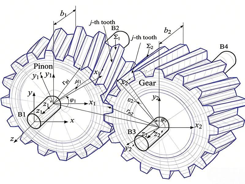
A helical gear is a cylindrical gear with teeth set at an angle to the gear axis. Its teeth enter and leave mesh gradually, which can reduce sudden engagement and help a transmission run smoothly. The details of helical gear design—including helix angle, tooth geometry, and the way the mating gears are arranged—affect how the gear set performs.
Parallel-axis helical gears are commonly used in industrial gearboxes, vehicle transmissions, and other drives that need steady power transfer.
Smooth Engagement
Gradual tooth contact can reduce impact during operation.
Load-Sharing Potential
With a suitable design, more than one pair of teeth may share the load during meshing.
Axial Thrust
A single helical gear mesh produces axial force, so bearings and the housing must be designed to support it.
Gear accuracy, shaft alignment, lubrication, and bearing arrangement also affect performance. Tooth shape alone does not determine how a gear set will behave in service.
What Are Screw Gears?
Screw gears are commonly called crossed helical gears. They are typically a pair of cylindrical helical gears mounted on skew shafts—shafts that are neither parallel nor intersecting.
This arrangement allows motion to pass between shafts set at an angle. Unlike a conventional parallel-axis helical gear pair, screw gears usually have localized tooth contact. The contact patch changes under load and elastic deformation, but it is generally more limited than the line contact found in a properly designed parallel-axis pair.
Screw gears, also called crossed helical gears, differ from worm gears in tooth geometry and meshing behavior. They are useful for transmitting motion between skew shafts, but their localized tooth contact and sliding action require careful consideration of load capacity, lubrication, and wear, especially in continuous operation.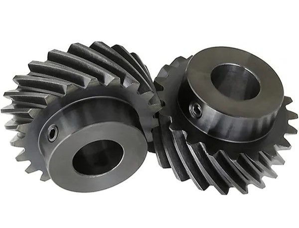
Screw Gears and Helical Gears: Key Differences
The main differences come from shaft arrangement, tooth contact, and operating conditions—not simply from the appearance of the teeth.
| Factor | Parallel-Axis Helical Gears | Screw Gears (Crossed Helical Gears) |
|---|---|---|
| Shaft arrangement | The shafts are parallel. | The shafts are skew: neither parallel nor intersecting. |
| Gear arrangement | Two helical gears mesh on parallel shafts. | Two helical gears mesh on skew shafts. |
| Tooth contact | Typically line contact, depending on geometry and load. | Typically localized contact; the contact patch changes under load. |
| Load capacity | Often better suited to higher-load power transmission when properly designed. | Usually more limited by contact stress and sliding. |
| Running behavior | Gradual engagement can support smooth transmission. | Depends strongly on design, alignment, lubrication, and operating conditions. |
| Sliding | Sliding occurs; its extent depends on design and mesh position. | Sliding is a key design consideration. |
| Lubrication | Specified according to load, speed, temperature, and gear design. | Requires particular attention to sliding, wear, and heat. |
| Typical uses | Industrial gearboxes, vehicle transmissions, and general power transmission. | Light-duty mechanisms and applications with specific skew-shaft layouts. |
How Shaft Arrangement Affects Gear Selection
Start by confirming the relative positions of the shafts. This is one of the first gear design requirements because it helps determine which gear arrangement is practical.
When the Shafts Are Parallel
A parallel-axis helical gear pair is often worth evaluating when the shafts are parallel and the system needs smooth, continuous power transmission. The design review should cover module, tooth count, helix angle, face width, center distance, and the axial loads that the bearings must support.
The final choice also depends on the required ratio, available space, duty cycle, and the rest of the transmission design.
When the Shafts Are Skew
When the shafts are neither parallel nor intersecting, crossed helical gears may provide a suitable layout. However, a flexible shaft arrangement does not mean the gear set can carry a high load.
Check contact stress, sliding, lubrication, wear, and expected service life. If the application transmits high torque continuously, compare other gear arrangements before choosing screw gears based on shaft angle alone.
Common Selection Mistakes
Choosing by Tooth Appearance Alone
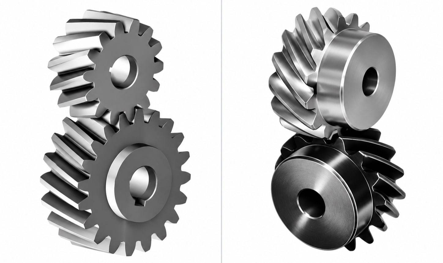
Both arrangements can have angled teeth, so appearance alone is not enough to identify how they will work. Confirm whether the shafts are parallel, intersecting, or skew before selecting the gear type.
Ignoring Tooth Contact and Accuracy
Load capacity depends in part on how the teeth contact each other. Screw gears usually have a smaller contact area than a properly designed parallel-axis helical gear pair, so their load capacity should not be assumed to be the same. Appropriate gear accuracy control helps keep key tooth geometry and mounting relationships within specified requirements.
Overlooking Lubrication and Wear
Sliding in crossed helical gears can contribute to wear and heat if the lubrication method is unsuitable. Confirm the lubricant, supply method, operating speed, temperature range, and maintenance expectations.
Confusing Screw Gears with Worm Gears
Screw gears and worm gears use different tooth geometries and meshing arrangements. Do not treat them as interchangeable based only on appearance or shaft angle.
Buyer Checklist: What to Confirm Before Ordering Custom Gears
If you are developing a new mechanism or sourcing replacement gears, prepare the following information before requesting a quote.
| Item | What to Confirm |
|---|---|
| Shaft arrangement | Shaft directions, angle between shafts, and shaft positions. |
| Gear type | Parallel-axis helical gears or crossed helical gears. |
| Gear geometry | Module, tooth count, pressure angle, helix angle, face width, and relevant dimensions. |
| Load and speed | Rated torque, peak load, operating speed, and duty cycle. |
| Material | Material grade and suitability for the operating conditions. |
| Lubrication | Lubricant, supply method, and operating temperature. |
| Accuracy | Tooth accuracy, critical dimensions, tolerances, and assembly requirements. |
| Quantity | Sample quantity, expected production volume, and future demand. |
If an existing gear has worn or failed, include photos of the part, details of the mating gear, and a description of the failure. These details can help distinguish material, lubrication, alignment, and design-related issues.
What to Include in a Gear Design Review
A useful review should connect the gear drawing to the real operating conditions. In addition to the basic dimensions, confirm the shaft layout, torque and speed range, duty cycle, lubrication method, operating temperature, expected life, and any restrictions imposed by the housing or bearings.
If the gear is part of an existing assembly, mating-part data and the current contact pattern may also help. Measurements taken from a worn gear should be treated carefully because wear can change the original geometry.
These inputs help the supplier identify what is known, what still needs confirmation, and which manufacturing or inspection requirements matter most.
Manufacturing and Inspection Considerations
The manufacturing route should match the gear geometry, material, accuracy requirements, and intended application. Cutting quality, heat-treatment distortion, finishing allowance, and inspection references can all affect the final gear.
Inspection may cover critical dimensions, runout, tooth profile, lead, pitch, tooth thickness, and other items specified for the project. Not every gear requires the same inspection scope; it should be agreed upon according to the drawing and application.
For custom projects, a clear specification makes it easier to compare quotations and reduces the risk of misunderstandings about what will be manufactured and checked. See also how to compare custom gear quotations.
Custom Gear Options for OEM Projects
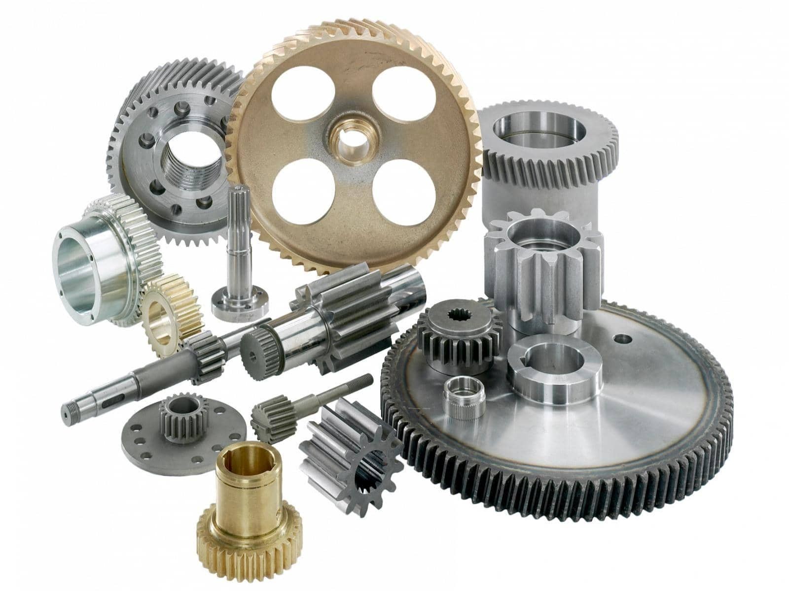
For projects involving conventional cylindrical gears, PairGears provides custom cylindrical gears and shafts based on drawings, samples, and application requirements. The product range includes spur gears, helical gears, internal gears, gear shafts, and spline shafts.
For a new design or a replacement part, prepare a gear drawing or 3D model, shaft arrangement, operating load and speed, material requirements, accuracy and inspection needs, and expected quantity. These details provide a more useful starting point for technical review.
For crossed helical gear projects, the specific design and manufacturing requirements should be reviewed before feasibility is confirmed. Capabilities used for conventional helical gears should not automatically be assumed to apply to every crossed-axis arrangement.
Frequently Asked Questions
Are screw gears and helical gears the same?
Not exactly. Screw gears, also called crossed helical gears, are a particular arrangement of helical gears used on skew shafts. In this article, “helical gears” refers to conventional parallel-axis helical gear pairs.
What is the main difference between screw gears and helical gears?
The main difference is the shaft arrangement and resulting tooth contact. Parallel-axis helical gears are generally better suited to higher-load power transmission, while screw gears are often used for lighter-duty applications that require skew shafts.
Can screw gears handle heavy loads?
Screw gears generally have more limited load capacity because their teeth have localized contact and experience sliding. Suitability depends on the design, material, lubrication, speed, and operating conditions.
Do screw gears need lubrication?
Lubrication is important because relative sliding can contribute to friction, wear, and heat. The suitable lubricant and supply method depend on the gear materials, load, speed, and operating environment.
Are screw gears the same as worm gears?
No. Screw gears typically use a pair of crossed helical gears. Worm gears use a worm and a mating worm wheel, with different tooth geometry and meshing behavior.
Conclusion
Screw gears and conventional parallel-axis helical gears both use angled teeth, but their shaft arrangements lead to different contact conditions and performance limits. Parallel-axis helical gears are commonly used for smooth power transmission and applications requiring higher load capacity. Screw gears are useful when motion must be transmitted between skew shafts and the load and speed suit the design.
Before choosing either arrangement, confirm the shaft layout, load, speed, lubrication, material, and expected service life. A clear drawing and realistic operating data provide the best starting point for a technical review.
Review Your Custom Gear Project With PairGears
If you are planning a custom gear project, contact us with your drawing, shaft layout, operating conditions, and required quantity to help determine the appropriate gear arrangement and manufacturing requirements.