What Should Be Included in a Custom Gear Drawing
- Share
- publisher
- PairGears
- Issue Time
- Sep 25,2026
Summary
Learn what information a custom gear drawing should include, from gear geometry and materials to heat treatment, accuracy, and inspection requirements.
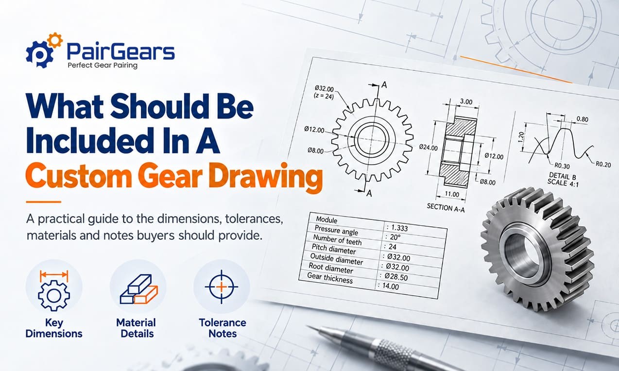
When sourcing custom gears, many buyers focus first on the gear type, material, or price. However, before manufacturing starts, one of the most important factors is whether the supplier has enough information to understand the part correctly. A missing tolerance, unclear heat treatment requirement, or incomplete tooth specification can affect quotation accuracy, manufacturing decisions, and even the final assembly performance.
A well-prepared custom gear drawing helps suppliers clearly understand your requirements and select the right manufacturing process for the project. At PairGears, we work with customers from different industries to review drawings, 3D models, and existing samples, helping turn design requirements into practical manufacturing plans. In this article, we will explain the key information that should be included in a custom gear drawing before sending an RFQ.
Custom Gear Drawing: Quick Checklist
A manufacturing-ready custom gear drawing usually includes the following information:
| Item | Required Information |
|---|---|
| Gear Type | Spur gear, helical gear, bevel gear, worm gear, etc. |
| Gear Geometry | Number of teeth, module/diametral pitch, pressure angle, helix angle, etc. |
| Dimensions | Outside diameter, bore size, face width, mounting dimensions |
| Material | Material grade and related requirements |
| Heat Treatment | Heat treatment method, hardness, case depth, etc. |
| Accuracy Requirements | Accuracy grade and tolerance requirements |
| Inspection Requirements | Inspection items and report requirements |
Without these details, suppliers usually need additional clarification before they can provide an accurate quotation and manufacturing plan.
Why Are Gear Drawings Important for Custom Manufacturing?
Custom gears are different from standard off-the-shelf components.
Standard gears usually have fixed specifications, while custom gears need to be manufactured according to the machine structure, load conditions, and operating environment. A supplier needs to understand not only what the gear looks like, but also how it will perform in the application.
For buyers, providing complete information also reduces quotation differences between suppliers and prevents misunderstandings during production.
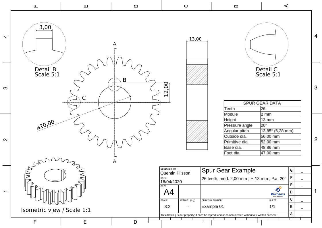
Gear Type and Basic Identification Information
The first step is clearly identifying the gear type.
Different gear types require different manufacturing approaches.
Therefore, defining the gear type is the foundation of a successful custom gear project.
Gear Geometry Information
Gear geometry is one of the most important parts of a manufacturing drawing. A typical gear drawing should include:
Number of Teeth
The number of teeth determines the transmission ratio and affects the overall gear size.
Module or Diametral Pitch
Module and diametral pitch define the size relationship of gear teeth.
Metric systems commonly use Module, while inch-based systems commonly use Diametral Pitch.
Pressure Angle
The pressure angle affects gear engagement, load capacity, and design space.
Helix Angle and Hand
For helical gears, the drawing should specify the helix angle and left-hand or right-hand direction.
Face Width
Face width affects load capacity and tooth contact area.
Without these parameters, it is difficult for manufacturers to determine proper machining conditions.
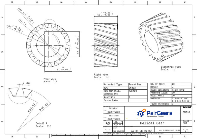
Critical Dimensions and Assembly Requirements
A gear must not only meet dimensional requirements but also fit correctly into the final assembly.
Important dimensions should include:
For gear shafts or integrated components, additional details may be required:
A gear with correct dimensions may still fail in operation if assembly references are unclear.
Material and Heat Treatment Requirements
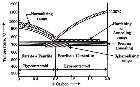
Material selection and heat treatment directly influence gear strength, wear resistance, and service life. A gear drawing should normally specify:
Material Grade
Common material options include:
▷ Carbon steel
▷ Alloy steel
▷ Stainless steel
▷ Bronze
The final material choice depends on factors such as load, speed, environment, and cost requirements.
Heat Treatment
Common heat treatment processes include:
▷ Carburizing
▷ Induction hardening
▷ Quenching and tempering
For gears requiring high wear resistance, drawings may also specify surface hardness, core hardness, and case depth.
These details help manufacturers develop an appropriate machining and inspection plan.
Gear Accuracy and Tolerance Requirements
Many buyers simply describe a product as a “high precision gear,” but this information is not specific enough for manufacturing.
Gear accuracy should preferably be defined according to recognized standards, such as:
Key tolerances may include:
Accuracy requirements should match the actual application. General industrial transmission systems may focus more on reliability and cost, while high-speed equipment may require better control of noise and tooth errors.
Higher accuracy is not always necessary for every application. The right specification depends on the actual working conditions.
Surface Finish and Tooth Requirements
Tooth surface quality affects:
Depending on application requirements, drawings may specify surface roughness requirements, tooth finishing requirements, and grinding requirements.
For high-precision gear projects, tooth profile inspection and lead inspection may also be required.
Inspection Requirements
A complete custom gear drawing should also define quality inspection requirements.
| Inspection Item | Purpose |
|---|---|
| Dimensional inspection | Verify critical dimensions |
| Tooth profile inspection | Check tooth form accuracy |
| Tooth lead inspection | Check lead deviation |
| Runout inspection | Verify rotational accuracy |
| Hardness testing | Confirm heat treatment results |
| Material verification | Confirm material properties |
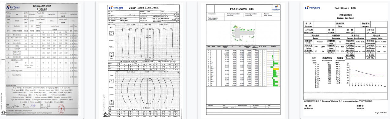
For projects with specific quality requirements, buyers can also define inspection report format, material certificates, hardness reports, and gear measurement reports.
What If You Do Not Have a Complete Gear Drawing?
Not every customer has a complete engineering drawing. In many real-world projects, requirements come from replacement of worn machine parts, discontinued components, OEM part number sourcing, or existing gear samples.
In these situations, customers can provide:
Manufacturers can then evaluate the available information and develop a suitable manufacturing solution.
Custom Gear Drawing Checklist Before Sending an RFQ
Before sending an inquiry, buyers can check whether the following information is available:
The more complete the information provided, the easier it is for suppliers to evaluate the project and prepare an accurate quotation.
How PairGears Reviews Custom Gear Projects
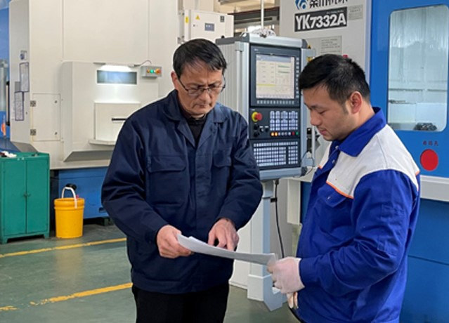
PairGears does not simply quote based on drawings. We evaluate each project from a manufacturing and application perspective.
During the early project stage, we review whether drawing information is complete, whether material and heat treatment are suitable, whether machining processes can achieve the required accuracy, and whether inspection methods match customer expectations.
Early technical clarification helps reduce modification risks and ensures smoother project execution.
FAQ About Custom Gear Drawings
What information is required for a custom gear quote?
A custom gear quotation usually requires gear type, dimensions, material, heat treatment, quantity, accuracy requirements, and inspection requirements.
Can you manufacture gears without a drawing?
Yes. Customers can provide samples, photos, OEM part numbers, or 3D models. The manufacturing plan can be developed after technical evaluation.
Is a 3D model enough for gear manufacturing?
A 3D model provides important geometry information, but additional details such as material, tolerances, and inspection requirements may still be required.
What happens if some gear specifications are missing?
The supplier should review the available information and confirm missing details before manufacturing to avoid incorrect assumptions.
Why are inspection requirements important for custom gears?
Inspection requirements define how final gear quality will be verified and help ensure the product meets assembly and application requirements.
Conclusion
A complete custom gear drawing is the foundation of accurate quotation and reliable manufacturing. It helps suppliers understand not only the gear dimensions but also the performance requirements behind the application.
Whether you have a complete drawing, a 3D model, or only an existing sample, PairGears can help evaluate your project requirements and develop a suitable manufacturing solution.
Need a Custom Gear Drawing Review?
Send your drawing, sample photos, or OEM information to PairGears for a technical review and quotation.