Helical Gear Types and Applications
- Share
- publisher
- Jessica
- Issue Time
- Dec 1,2025
Summary
Learn the main types of helical gears, how tooth design affects load capacity, and where they are used in agricultural, truck, construction and EV.

1.Introduction
Helical gears are a core element in many modern powertrains. By cutting the teeth at a helix angle instead of straight across the face, they increase contact ratio, smooth out torque transfer and improve load distribution compared with spur gears. For OEMs and system integrators in agricultural machinery, heavy truck, construction equipment and electric vehicle(EV), choosing the right helical gear types is a key part of achieving durable, efficient drivelines.
As a precision gear manufacturer and custom gear supplier, PairGears designs and produces helical gears, shafts and related components for demanding off-highway and on-road applications. This article outlines the main types of helical gears, the tooth design options behind them, and how they are used across PairGears'four focus sectors.
2.The Role of Helical Gears in Power Transmission
Helical gears are a type of cylindrical gear whose tooth lines are cut at a helix angle relative to the gear axis. Compared with spur gears, they offer:
Smoother meshing – teeth come into contact gradually along the face width.
Higher load capacity – multiple teeth share the load at any given moment.
Better load distribution – longer contact lines help reduce local stress peaks.
One trade-off is that single helical gears generate axial thrust, which must be handled by the bearing and housing design. When this is properly managed, helical gears provide a robust balance of strength, smooth running and efficiency for a wide range of industrial and vehicle applications.

3. Main Types of Helical Gears
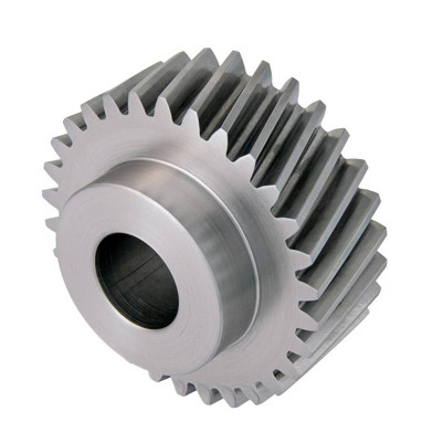
3.1 Single Helical Gears
Single helical gears are the most common form:
-Tooth lines all have the same helix angle and the same hand (left-hand or right-hand).
-A helical pair on parallel shafts normally uses one left-hand and one right-hand gear with equal helix angles.
-Axial thrust must be supported by the bearing arrangement.
Single helical gears are widely used where space is limited but smoother operation and higher torque capacity are required than spur gears can offer. In PairGears projects, they are common in auxiliary drives, medium-duty transmission stages and various shaft-to-shaft connections.

3.2 Double Helical / Herringbone Gears
Double helical gears, often referred to as herringbone gears, combine a left-hand and a right-hand helical section on the same gear body:
-The opposing helix hands cancel axial thrust in normal operation.
-Overall contact area is increased, and load sharing between teeth is improved.
-They are well suited to heavy-duty, high-torque, long-life drive stages.
Because of their geometry, double helical gears place higher demands on machining and assembly accuracy, but in return they provide very stable torque transfer in high-load industrial and vehicle drivelines.
3.3 Left-Hand and Right-Hand Helical Pairs
Looking along the shaft, helical teeth may spiral:
-Left-hand – tooth lines spiral anticlockwise,
-Right-hand – tooth lines spiral clockwise.
For two helical gears on parallel shafts to mesh correctly:
-Helix angles must have the same magnitude, Helix hands must be opposite (one left-hand, one right-hand) Module, pressure angle and tooth profile must also match.
In PairGears design reviews, helix angle, hand, module and tooth count are always checked together, to ensure that helical gear pairs will mesh correctly in the actual center distance and bearing layout.

4. Tooth Design Options and Their Impact
Beyond basic geometry, tooth design strongly affects the performance and life of helical gears.
4.1 Standard Helical Tooth Profiles
Standard helical gears use:
-standard modules
-standard involute profiles
-no profile shift or special modification
They are suitable for many general-purpose drives where loads are moderate, running conditions are stable and cost efficiency is important. For many mainstream agricultural and truck transmissions, carefully selected standard helical designs already provide an excellent balance of strength and cost.
4.2 Modified Helical Teeth
Modified helical teeth introduce controlled changes to the basic tooth form, such as:
-Lead crowning to improve load distribution across face width,
-Profile modification to reduce edge contact and impact at mesh entry/exit,
-Chamfers and tip relief to reduce sensitivity to minor misalignment or burrs.
For heavy-duty or long-life applications, PairGears combines tooth modification with tooth contact analysis and physical contact-pattern checks to achieve more robust load sharing and lower risk of edge overload or local surface damage.
4.3 Profile-Shifted Helical Gears
Profile shifting moves the tooth profile radially inward or outward without changing the base involute form:
-Positive profile shift can help thicken tooth roots and reduce undercut risk.
-Negative profile shift can help control outside diameter or satisfy restricted center distances.
-Combined profile shifts on mating gears help manage backlash, overlap ratio and load capacity.
In complex programs, such as compact off-highway drives or combined reduction stages, profile-shifted helical gears are a useful tool for reconciling limited package space, high torque targets and desired life.
4.4 Involute Helical Tooth Form
Most modern helical gears use an involute profile:
-Conjugate geometry supports nearly constant transmission ratio.
-Manufacturing and inspection practices are well established.
-Surface fatigue and wear behaviour is predictable when lubrication is properly engineered.
PairGears designs tooth forms to meet relevant standards (for example ISO, DIN or AGMA), and uses gear measurement, lead/profile analysis and contact-pattern evaluation to verify that the manufactured gears match the intended design.
5. Helical Gears in the Four PairGears Sectors
The table below summarises how helical gears are typically used across PairGears'four focus sectors, and what the main design concerns are.
| Sector | Typical helical gear positions | Duty profile | Key design focus |
Agricultural machinery | Transmission stages, PTO drives, differential input gears | Shock loading, dust, long work hours | Load capacity, wear resistance, tolerance of contamination |
| Heavy truck | Transmission gears, axle input gears, synchronizer hubs | High mileage, heavy loads, mixed cycles | Strength, durability consistency, efficiency over long service |
| Construction equipment | Axle reductions, swing and travel drives, heavy reducers | Low speed, high torque, frequent shocks | Tooth root strength, surface fatigue, safety margins |
| Electric vehicle(EV) | E-drive stages, axle input gears, secondary reduction sets | High speed, compact packaging | Precision, efficiency, thermal behaviour, packaging constraints |
In all of these programs, PairGears evaluates helical gear design together with shaft layout, bearings, materials, heat treatment and lubrication, rather than treating the gear as a stand-alone component.
6. Selecting and Customising Helical Gears with PairGears
When you work with PairGears on a helical gear solution, providing clear input data allows faster and more accurate proposals. Helpful information includes:
-Existing drawings or samples (tooth count, module, pressure angle, helix angle, face width, tolerances).
-Application sector and installation position (agricultural machinery, heavy truck, construction equipment or EV).
-Operating conditions: torque and speed range, duty cycle, target life.
-Center distances, shaft layout, bearing arrangement and lubrication concept.
-Target standards and quality levels (accuracy class, noise/vibration limits if applicable).
Based on this, PairGears can recommend tooth geometry, materials and heat treatment, and supply helical gears and matching shafts from prototypes through to series production.

7. Conclusion: Work with a Precision Gear Manufacturer You Can Trust
For modern powertrains, the choice and design of helical gear types has a direct impact on load capacity, durability and overall driveline performance. Understanding the differences between single helical, double helical and various tooth-design options helps engineers specify more robust and efficient systems.
As a precision gear manufacturer and custom gear supplier, PairGears develops and produces helical gears and related components for agricultural machinery, heavy trucks, construction equipment and EV applications. If you are evaluating the helical gears in an existing design or planning a new project and need to confirm geometry, load capability or manufacturing feasibility, Contact Us to discuss how PairGears can support your next helical gear program with practical, application-focused engineering and reliable production.
FAQ: Helical Gear Basics
Q1: Can helical gears directly replace spur gears?
Not always. Even if module and tooth count are similar, helical gears generate axial thrust and may alter center distance and contact conditions. Any change from spur to helical gears should be evaluated at system level, considering shafts, bearings and housing.
Q2: How can I judge whether helical gear contact is acceptable?
Engineers normally look at tooth contact patterns, backlash measurements and running behaviour under load. A well-designed helical pair shows centered, evenly distributed contact with no severe edge loading or abnormal wear.
Q3: Do EV applications require special helical gear designs?
EV drivelines often combine high rotational speeds with compact housings and strict efficiency targets. This calls for higher tooth accuracy, carefully controlled surface finish and a well-matched lubrication strategy, alongside suitable materials and heat treatment.