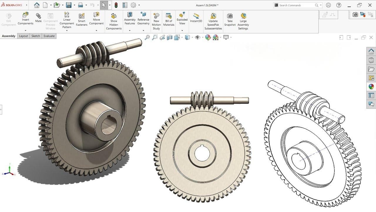
What is the difference between single-start and double-start worms?
- Share
- Issue Time
- Sep 14,2026
Single-start and double-start worms have one and two independent helical threads, respectively. In a correctly matched set, one worm revolution advances the wheel by one tooth for a single-start worm and two teeth for a double-start worm. With the same wheel tooth count, a double-start design halves the reduction ratio. It requires compatible wheel geometry.
Single-start and double-start worms: count the threads
A start is one continuous thread winding around the worm. It is not the number of grooves visible along its length, and it does not indicate right-hand or left-hand rotation.
For the worm driving the wheel, the reduction ratio is i = wheel tooth count ÷ worm starts. Thread count describes ratio; thread hand is a separate specification.
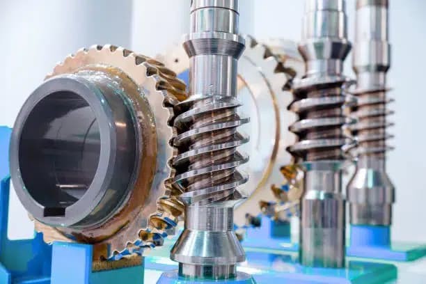
The photograph illustrates worm-and-wheel components, not a verified comparison of their start counts.

Same wheel tooth count, different reduction
| 40-tooth wheel | Single start | Double start |
|---|---|---|
| Ratio | 40:1 | 20:1 |
| Wheel speed at 1,200 rpm worm speed | 30 rpm | 60 rpm |
These are calculated speed examples for two properly matched designs, not instructions to swap worms in an existing gearbox.
At the same axial pitch, lead equals axial pitch × starts. With the same worm reference diameter, more starts give a larger lead angle.
Check the wheel and the operating condition
Specify the start count, hand, pitch system, pressure angle, center distance and matched wheel. A wheel made for one worm geometry may not mesh correctly with another.
Lead angle and friction affect efficiency and backdriving. Start count alone cannot establish self-locking; a holding function needs a separately verified design.
For a PairGears inquiry, include both component drawings and operating loads. The worm gear working-principle guide explains the pair.
Related questions