What is gear transmission?
- Share
- Issue Time
- Sep 14,2026
Gear transmission transfers motion and power through meshing gear teeth. Depending on the arrangement, it changes rotational speed, torque or direction, or converts rotation into linear travel with a rack. The tooth counts set the ideal speed relationship. Actual performance also depends on tooth geometry, alignment, lubrication, load and losses in the complete drive.
How gear transmission changes motion
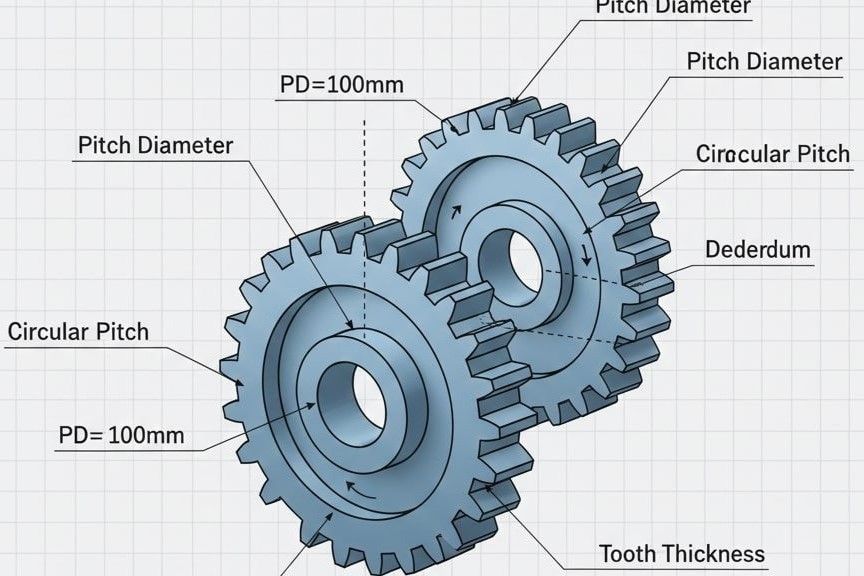
A driving gear pushes the teeth of its mating gear. In a simple fixed-axis pair, the ratio is determined by tooth counts. An external pair turns in opposite directions; an external pinion meshing inside an internal gear turns in the same direction.
- Parallel shafts: spur or parallel-axis helical gears.
- Intersecting shafts: bevel gears.
- Nonparallel, nonintersecting shafts: arrangements such as worm drives.
- Linear travel: a pinion drives a rack.
A simple 3:1 reduction example
For a fixed-axis pair with a 20-tooth driver and a 60-tooth driven gear:
i = 60 ÷ 20 = 3
At 900 rpm input, output speed is 300 rpm.
Ignoring losses, output torque is three times input torque. In practice, output torque is input torque × ratio × efficiency. This example is illustrative, not a PairGears performance rating.
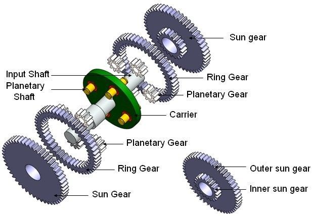
Do not apply this two-gear formula directly to a planetary set without identifying its operating arrangement.
What to specify for a working gear pair
Give PairGears the shaft layout, input speed, output torque, duty cycle, target ratio, available space and mating-part drawing. Geometry and mounting must be compatible; ratio alone does not establish load capacity.
Review the planetary transmission gear checklist for a compound assembly.
Related questions