What machines are used for gear cutting?
- Share
- Issue Time
- Aug 31,2026
Gear cutting machines: select the process from the part, not the label
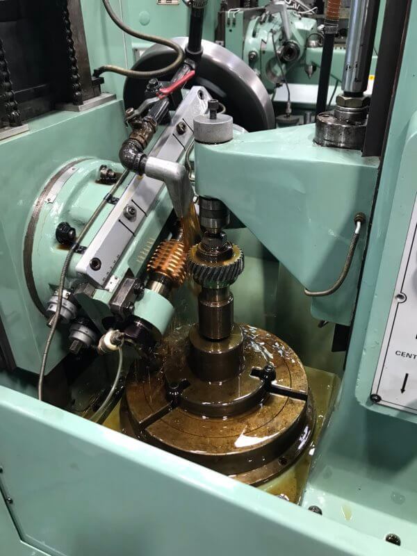
Gear cutting can use hobbing, shaping, milling, broaching, skiving or grinding equipment. The right machine depends on the tooth geometry, external or internal form, blank access, material condition, accuracy target, quantity and inspection method. PairGears should review the drawing and mating conditions before a process is assigned, because one machine type cannot cover every gear design.
Match the machine family to the geometry and route
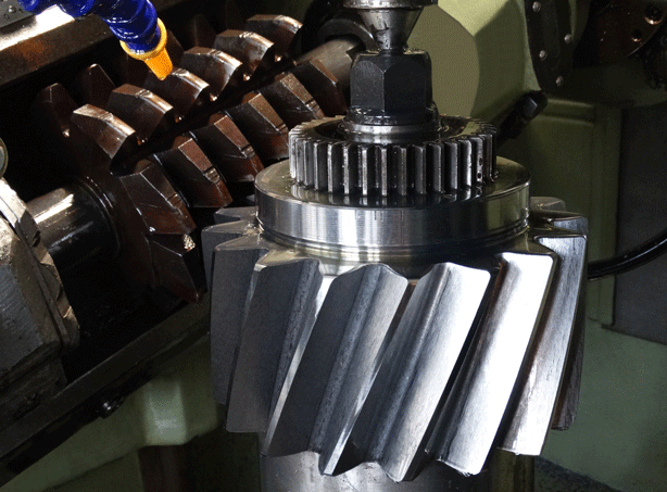
Hobbing is commonly used for many external spur and helical gears. Shaping can suit internal teeth or areas with limited tool runout. Milling may be practical for selected forms, prototype work or restricted quantities, while broaching can apply to suitable internal forms. Skiving and grinding are selected when geometry, material state or final tooth requirements make them appropriate.
The PairGears gear-cutting guide explains why the cutting step must connect to blank preparation, heat treatment, finishing and verification rather than be specified in isolation.

Example or decision check
For a hardened internal gear, the review may compare shaping or skiving before heat treatment with a hard-finishing route afterward. For an external helical gear, hobbing may be a starting point, but the final choice still needs the module or DP, pressure angle, helix data, face width, material route, quality target and measurement plan.