What is the difference between normal and transverse module in helical gears?
- Share
- Issue Time
- Aug 21,2026
Normal vs. transverse module: confirm the reference plane
Normal module is defined in the plane normal to a helical tooth, while transverse module is defined in the plane perpendicular to the gear axis. They are related through helix angle but are not interchangeable. Before selecting or replacing a mating gear, confirm the reference plane, pressure angle, helix angle and hand—not only the module value. PairGears uses the complete parameter set when a helical mesh is reviewed.
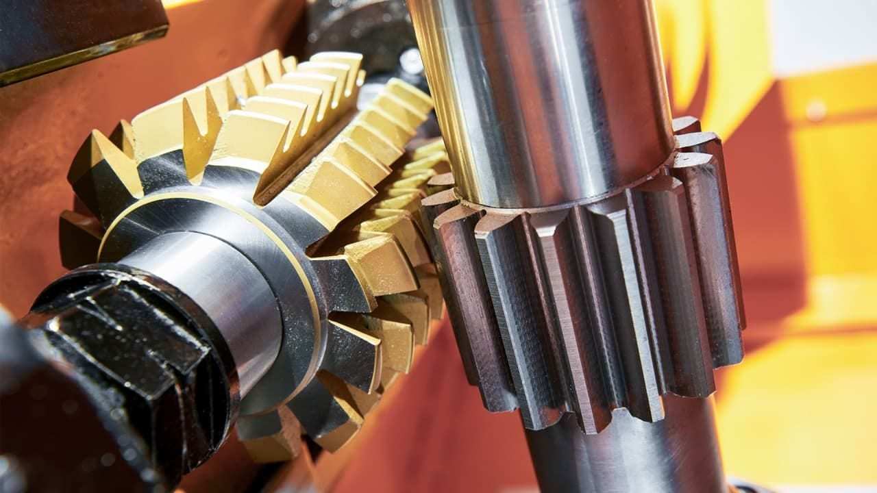
How to read the drawing safely
Look for the plane named by the drawing: a normal-system value is taken in the tooth-normal plane; a transverse-system value is taken in the plane perpendicular to the axis. With a nonzero helix angle, the values are linked mathematically, but a module label without its reference plane can lead to the wrong tooth form, pitch geometry or tooling choice.
For a mating helical pair, also confirm pressure-angle convention, helix angle, opposite hand, tooth count, center distance and any profile shift. The PairGears meshing guide notes that the normal module, helix angle, helix direction and mating geometry must agree; matching one value alone is not a fit check.
Example and decision check
Two helical gears can both be described as module 2 yet still fail to mesh if one value is normal and the other is transverse, or if their helix angles or hands differ. In a replacement project, ask for the original drawing or measure the complete tooth system before approving a substitute. Do not convert a value without recording the reference plane and helix angle used.