What information is needed for a gear calculation?
- Share
- Issue Time
- Aug 20,2026
Gear calculation inputs: establish the duty before the formula
A usable gear calculation needs more than module and tooth count. Define the gear type, ratio, torque, speed, duty cycle, layout, tooth system, material, lubrication, life target and accuracy requirement; mark any unknowns as assumptions before release. PairGears uses those inputs together because a correct equation can still answer the wrong load case.
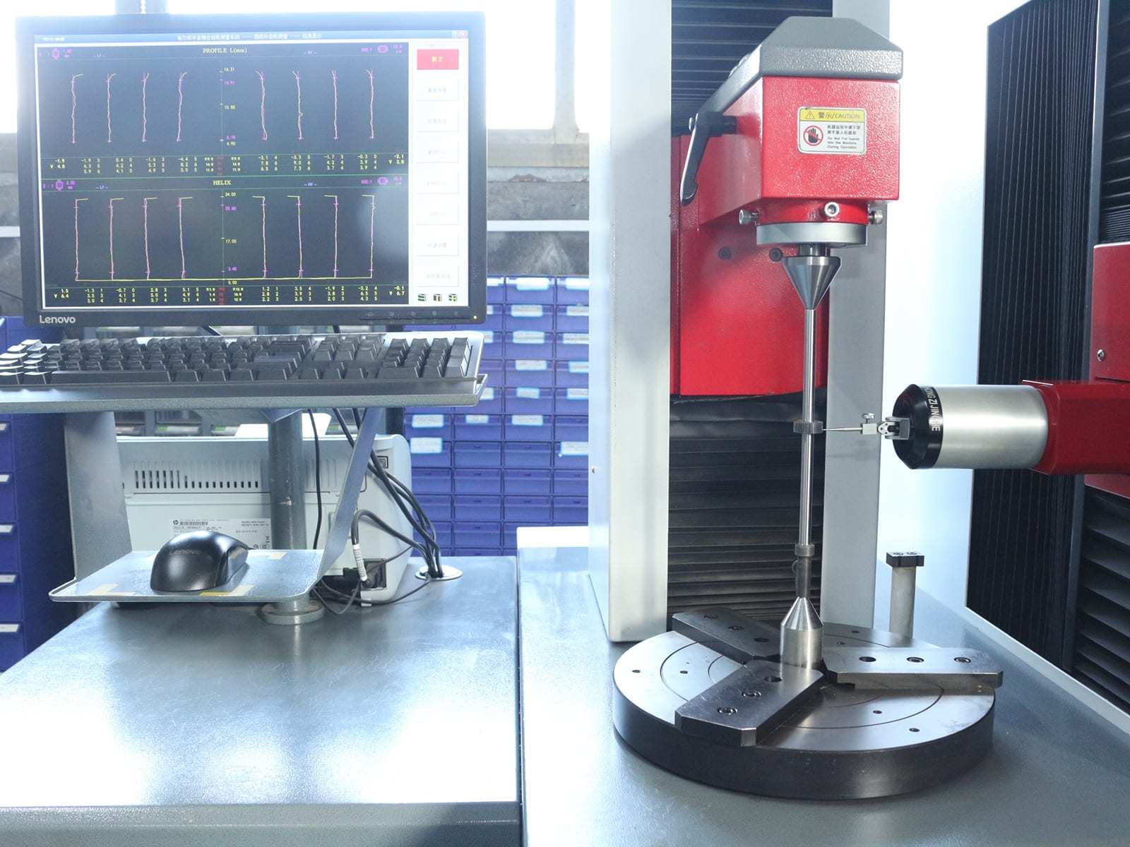
What to define before release
Start with the system: state the driver and driven members, desired ratio, available center distance or shaft angle, torque and speed range, duty cycle, shock loading, temperature and lubrication condition. Then specify module or DP, tooth count, pressure angle, helix angle where applicable, face width, material and heat-treatment condition.
Next define what the calculation must prove: bending strength, contact stress, pitch-line velocity, backlash, center distance, life, noise or manufacturability. The PairGears design reference notes that changing one parameter changes the meaning of the others, so a calculation should record its assumptions and mating-part data.
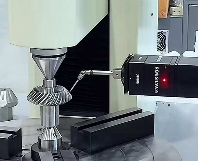
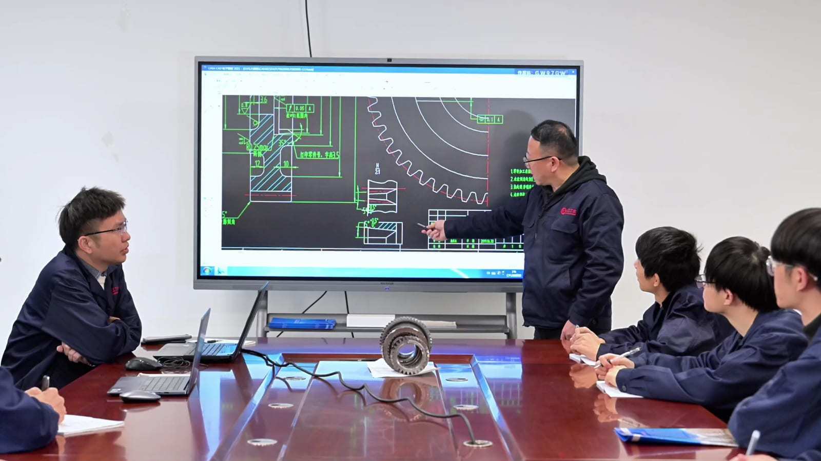
Example and decision check
For a spur pair with a 3:1 target ratio, 20 teeth on the pinion and 60 on the gear may establish the basic ratio; it does not by itself establish a safe design. The calculation still needs module, face width, torque, speed, material condition, load spectrum, center distance, lubrication and required life before bending and contact checks can be interpreted.