Gear Manufacturing & Inspection Equipment | PairGears
- Share
Manufacturing & Inspection Equipment
See the equipment used to machine, heat-treat, finish and inspect custom gears and shafts, together with the checks and report formats that can be planned for a project.
Quick Answer
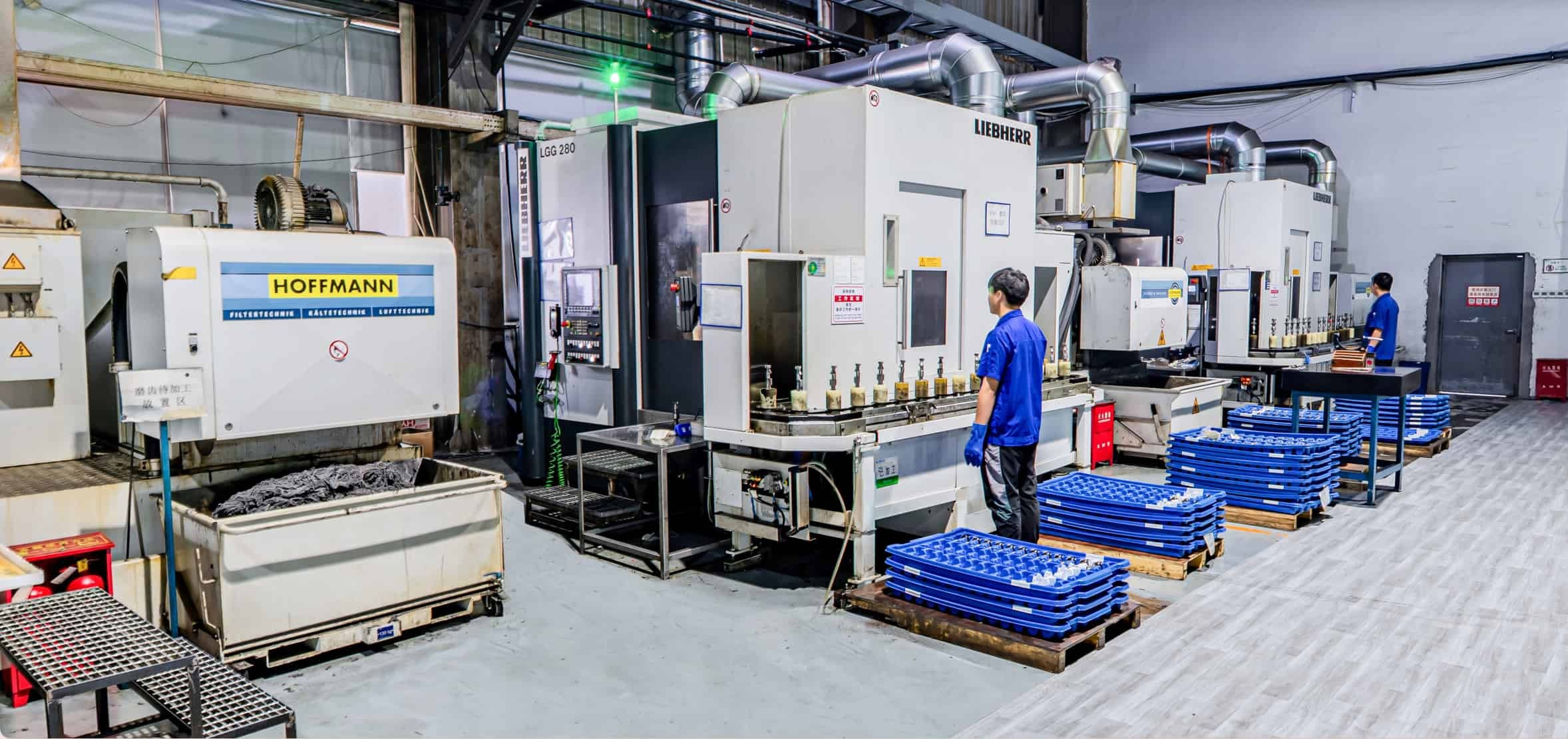
PairGears' documented equipment covers turning, spur and helical gear cutting, bevel gear milling, gear grinding, heat treatment, cleaning, dimensional measurement, material verification and gear-geometry inspection. The final process route and inspection plan are confirmed from the drawing, material, accuracy grade, application and agreed documentation requirements.
What buyers can verify here
An equipment name matters only when it is connected to the operation it performs, the feature it controls and the evidence a buyer may request.
How the part is made
Production equipment is grouped by its role instead of appearing as an unstructured photo gallery.
- Turning and datum preparation
- Spur, helical and bevel gear cutting
- Grinding, heat treatment and cleaning
What can be checked
Inspection equipment is tied to specific characteristics so buyers can judge whether it fits their drawing.
- Dimensions and geometric relationships
- Material composition
- Profile, helix, pitch and runout
What may be documented
Public report samples show the format and type of evidence available for selected projects.
- Dimensional inspection results
- Gear profile and helix report
- Hardness and metallographic report
From a drawing requirement to a record
The inspection route should follow the characteristics that affect fit, tooth contact, load distribution and material condition.
Visible dimensions
Profiles, edges, positions and selected two-dimensional features.
Vision measuring machine → dimensional resultsDimensions & GD&T
Three-dimensional features and drawing-defined geometric relationships.
CMM → dimensional / first-article reportMaterial identity
Chemical composition checked against the agreed metallic material requirement.
Spectrometer → composition recordTooth geometry
Profile, helix or lead, pitch and runout according to the inspection plan.
Gear measuring center → gear inspection reportEquipment by manufacturing stage
Review selected equipment in manufacturing-process order. This page shows representative equipment rather than the complete inventory. Machine allocation and acceptance criteria are confirmed after technical review.
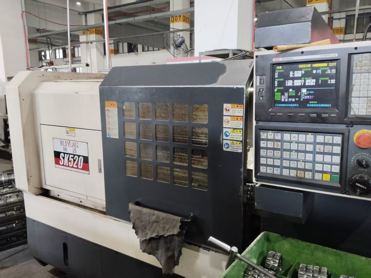
CNC Lathe
- Used for
- Machines faces, bores, outside diameters, shoulders and datum surfaces before tooth cutting.
- Control / output
- Builds the dimensional foundation used by later gear cutting, grinding and inspection steps.
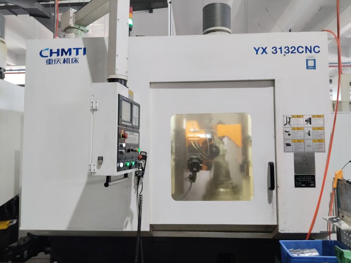
Gear Hobbing Machine
- Used for
- Cuts external spur and helical gear teeth and selected spline forms before heat treatment.
- Control / output
- Reference range: module 0.2-45; up to AGMA 10 / DIN 8 / JIS 4, subject to part review.
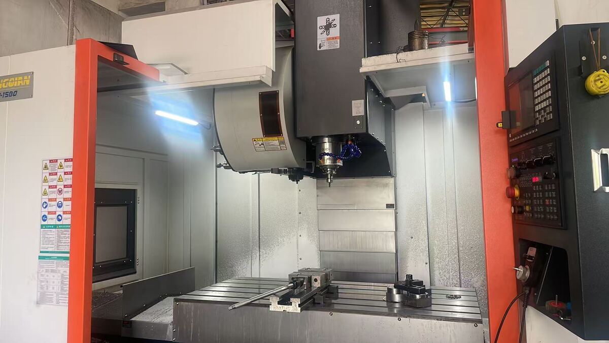
Bevel Gear Milling Machine
- Used for
- Mills bevel gear tooth spaces for selected prototypes and production projects before heat treatment.
- Control / output
- Machine selection and the cutting route are confirmed from the bevel gear geometry, drawing, material, accuracy target and batch size.
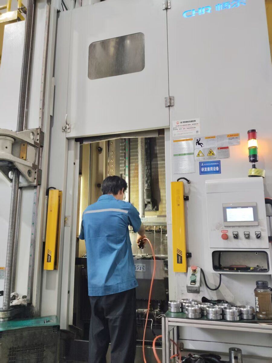
Vertical Broaching Machine
- Used for
- Produces internal splines, keyways and other through profiles with a vertical tool path.
- Control / output
- Used where repeatable internal geometry is required for assembly with mating shafts.
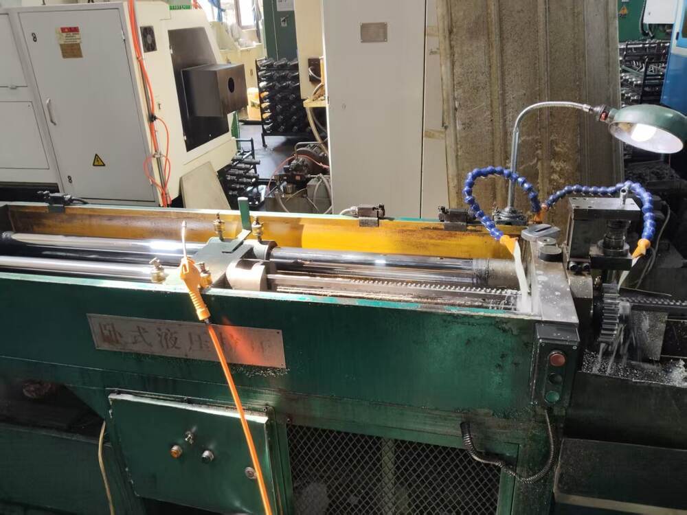
Horizontal Broaching Machine
- Used for
- Broaches internal splines, keyways and through features along a horizontal axis.
- Control / output
- Selected according to feature length, workholding, material and production route.
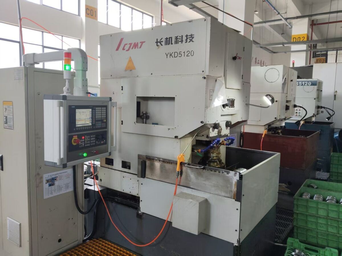
Gear Shaping Machine
- Used for
- Cuts internal gears and external teeth, including geometries close to shoulders.
- Control / output
- Reference range: module 0.5-25; up to AGMA 10 / DIN 8 / JIS 4 before heat treatment.
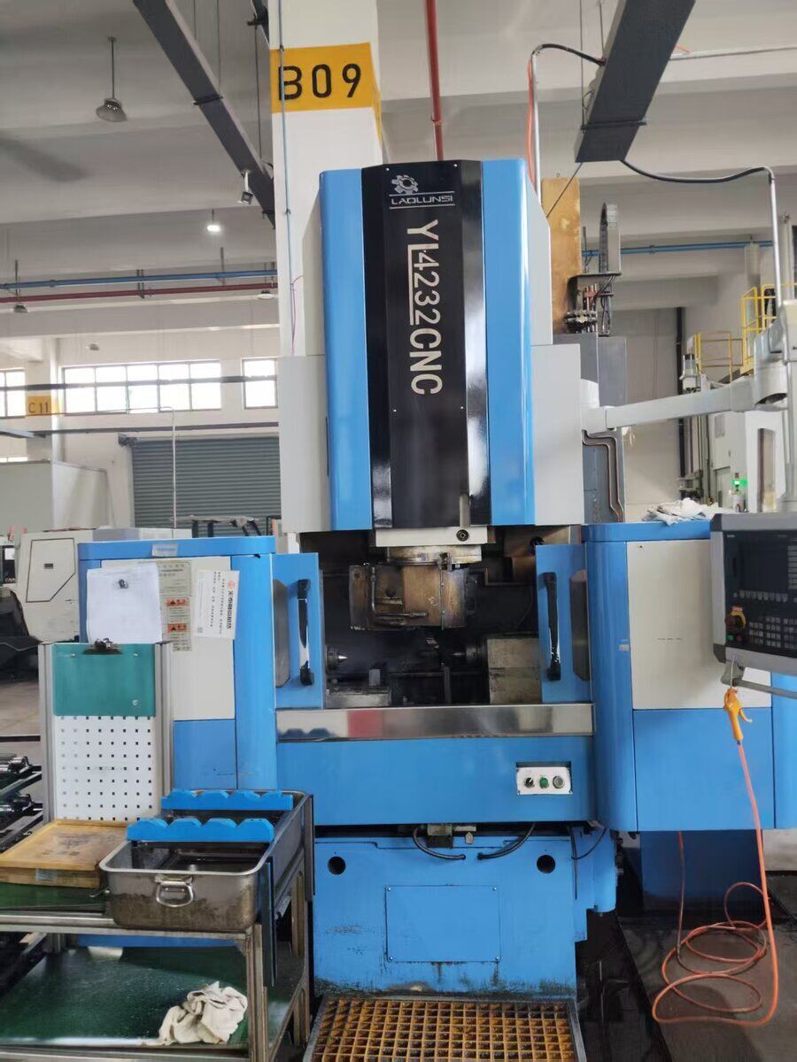
Gear Shaving Machine
- Used for
- Finishes tooth flanks before heat treatment to improve profile, lead and surface condition.
- Control / output
- Reference range: module 0.8-6; up to AGMA 11 / DIN 7 / JIS 3 before heat treatment.
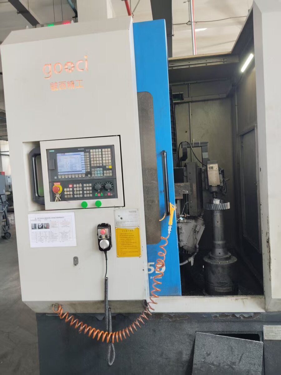
Gear Chamfering Machine
- Used for
- Forms controlled edge chamfers and removes sharp tooth-edge conditions after cutting.
- Control / output
- Chamfer design is matched to drawing requirements and downstream processing needs.
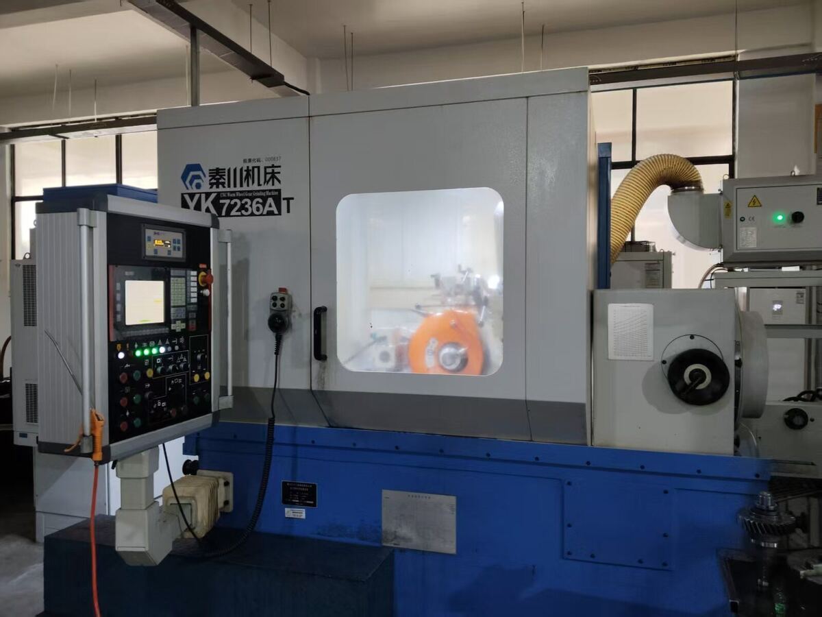
Continuous-Generating Gear Grinding Machine
- Used for
- Finishes hardened spur and helical gear teeth using a worm-shaped grinding wheel.
- Control / output
- Supports stable tooth correction and batch processing after heat treatment.
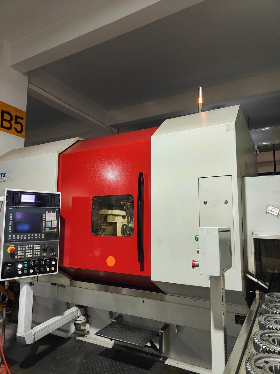
Profile Gear Grinding Machine
- Used for
- Grinds tooth flanks with a formed wheel for selected gear sizes and tooth geometries.
- Control / output
- Useful where profile flexibility or project-specific tooth correction is required.
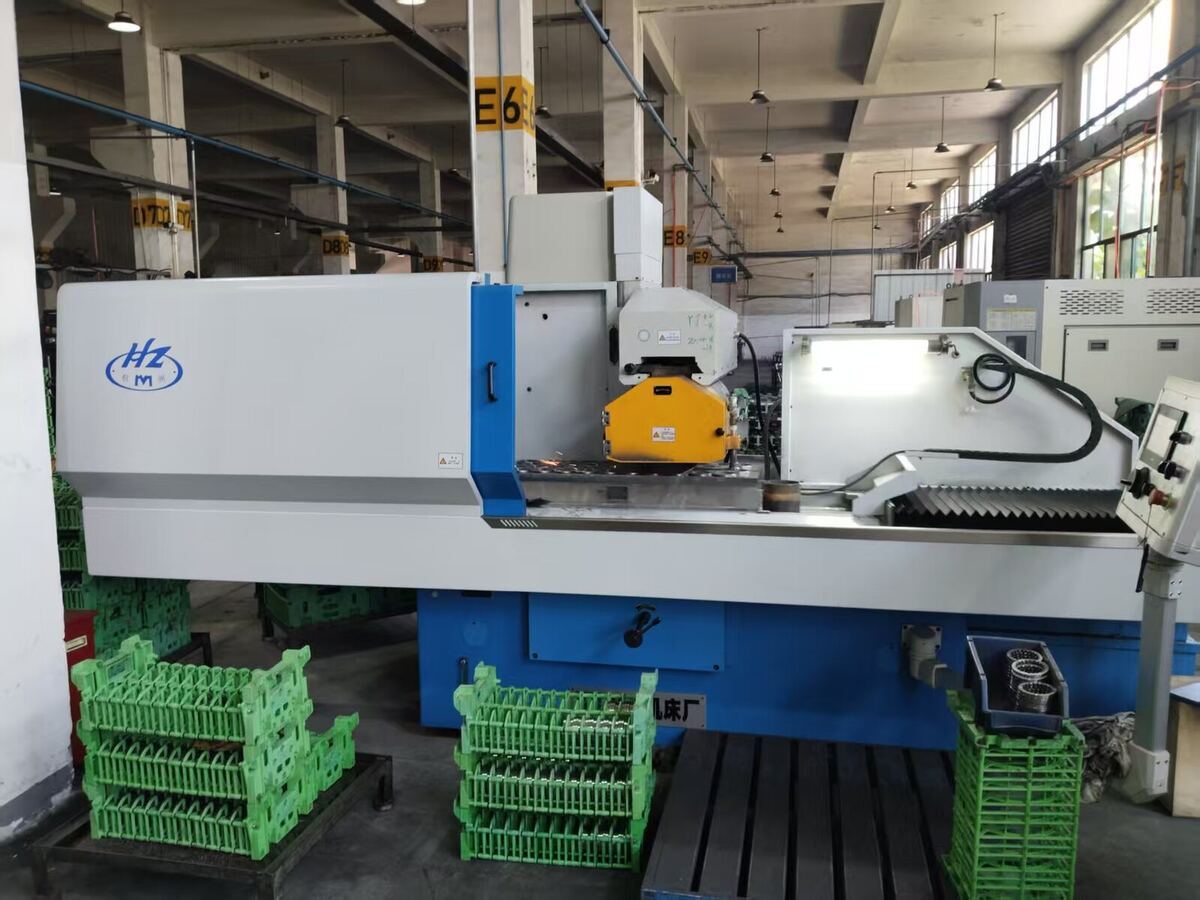
Surface Grinding Machine
- Used for
- Grinds flat functional faces used for seating, spacing or assembly reference.
- Control / output
- Applied when the drawing calls for controlled flatness, parallelism or surface finish.
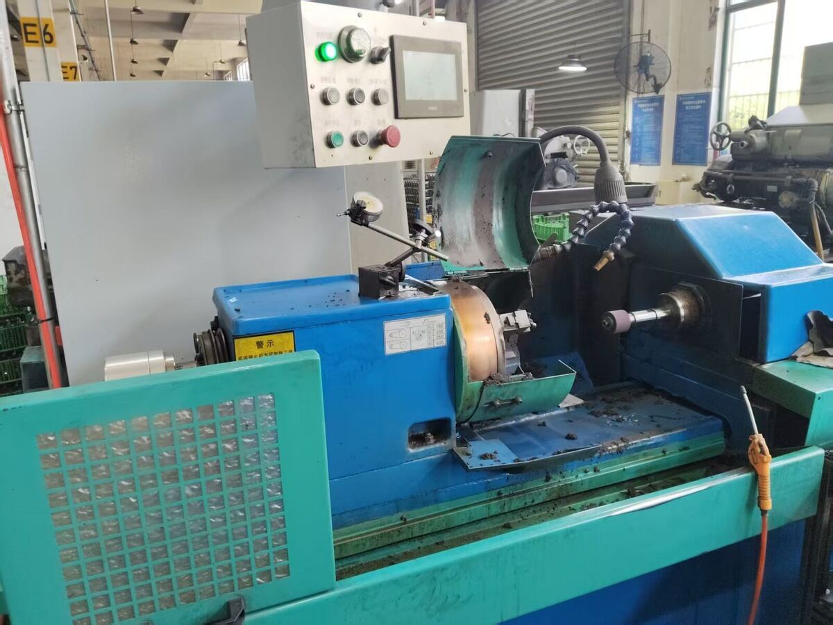
Internal Grinding Machine
- Used for
- Finishes bores and internal cylindrical surfaces after machining or heat treatment.
- Control / output
- Supports bore size, roundness and datum relationships required by the drawing.
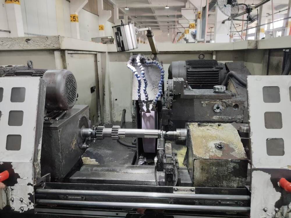
External Cylindrical Grinding Machine
- Used for
- Finishes journals, bearing seats and other external cylindrical surfaces.
- Control / output
- Used to control diameter, roundness, surface finish and relationships between datums.
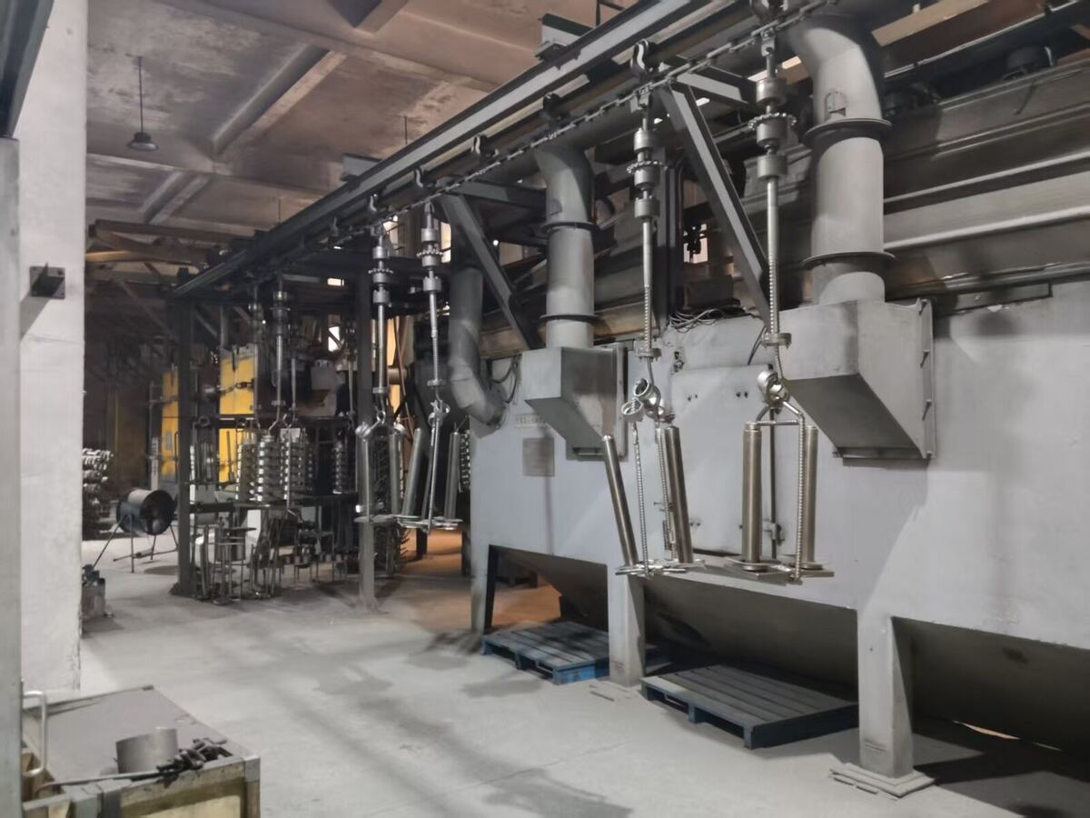
Shot Blasting Line
- Used for
- Cleans and conditions part surfaces after selected manufacturing or heat-treatment steps.
- Control / output
- Process settings are selected by material, surface condition and downstream requirements.
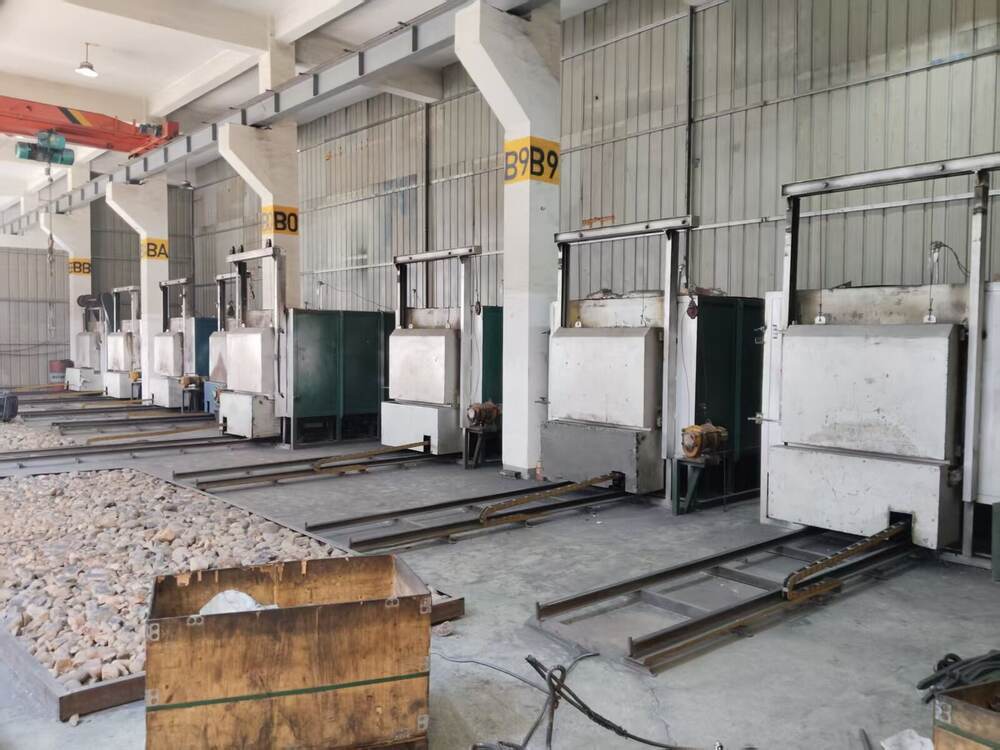
Normalizing Furnace
- Used for
- Supports normalizing routes used to prepare material structure for subsequent processing.
- Control / output
- The heat-treatment route is confirmed from material, drawing and performance requirements.
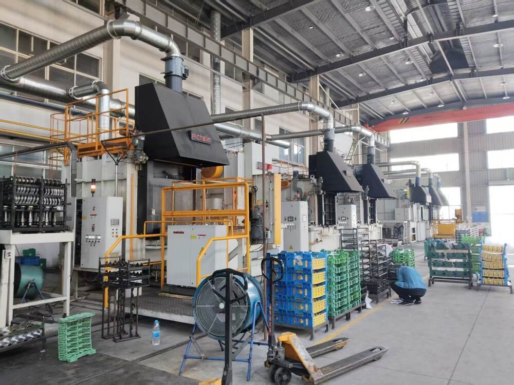
Sealed Quench / Multi-Purpose Furnace
- Used for
- Supports controlled heat-treatment cycles selected for the specified gear material and hardness target.
- Control / output
- Cycle, atmosphere and acceptance checks are defined in the project control plan.
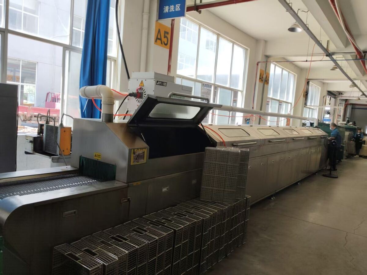
Ultrasonic Cleaning Line
- Used for
- Removes processing residue from parts before selected inspection, preservation or packing steps.
- Control / output
- Cleaning requirements depend on the part condition and the agreed delivery specification.
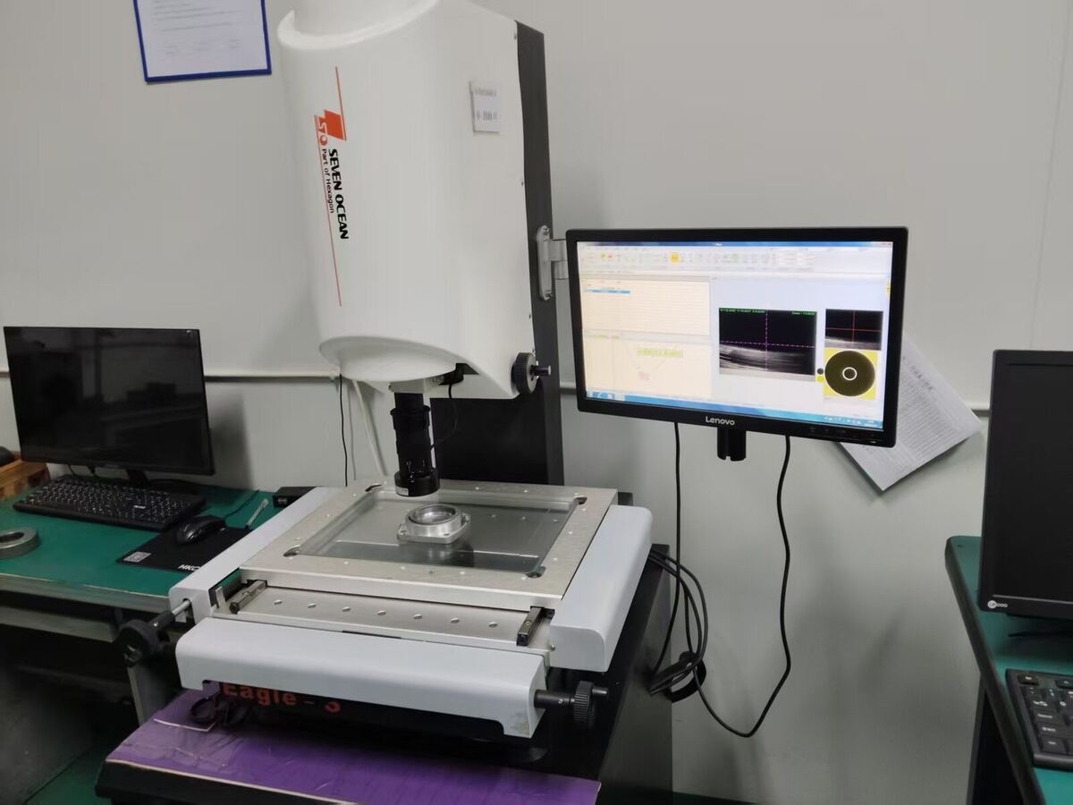
Vision Measuring Machine
- Used for
- Measures visible profiles, edges, positions and selected two-dimensional features.
- Control / output
- Typical output: recorded dimensional results for features within the approved method capability.
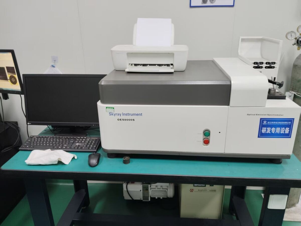
Optical Emission Spectrometer
- Used for
- Checks the chemical composition of metallic materials against the agreed material requirement.
- Control / output
- Typical output: material composition results or a supporting inspection record when specified.
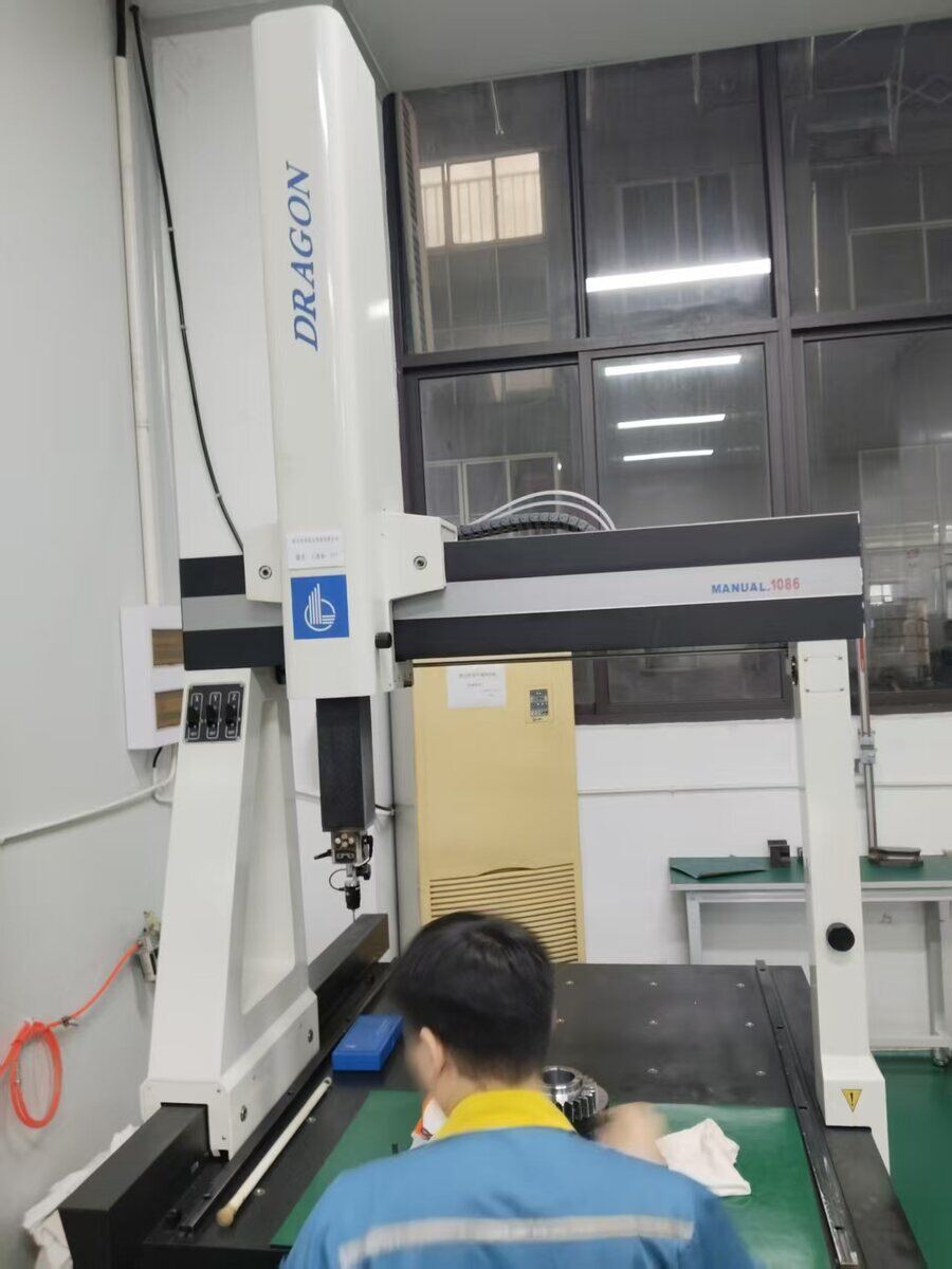
Coordinate Measuring Machine (CMM)
- Used for
- Measures three-dimensional features and drawing-defined geometric relationships.
- Control / output
- Typical output: dimensional inspection or first-article results for agreed characteristics.
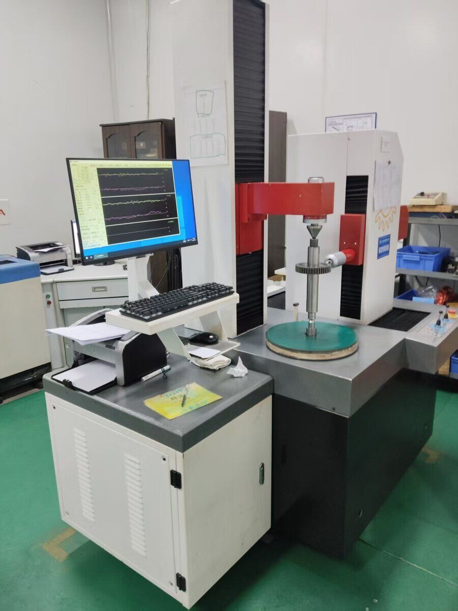
Gear Measuring Center
- Used for
- Evaluates tooth profile, helix or lead, pitch and runout according to the inspection plan.
- Control / output
- Typical output: gear profile and helix deviation report for agreed inspection characteristics.
Reference capability data
These ranges help with early screening. They do not replace a drawing review or a project-specific process and inspection plan.
| Gear / process | Condition | Reference quality | Pitch | Module |
|---|---|---|---|---|
| Spur & helical - Hobbing | Before heat treatment | AGMA 10 / DIN 8 / JIS 4 | 0.55-128 DP | M0.2-M45 |
| Spur & helical - Shaping | Before heat treatment | AGMA 10 / DIN 8 / JIS 4 | 1-48 DP | M0.5-M25 |
| Spur & helical - Shaving | Before heat treatment | AGMA 11 / DIN 7 / JIS 3 | 4-32 DP | M0.8-M6 |
| Spur & helical - Grinding | After heat treatment where required | AGMA 14 / DIN 4 / JIS 0 | 1-32 DP | M0.8-M25 |
| Spur & helical - Power honing | Finishing route | AGMA 12 / DIN 6 / JIS 2 | 1-128 DP | M0.2-M20 |
| Spiral bevel - Cut & lap | Before heat treatment | AGMA 10 / DIN 8 | 1-10 DP | M2.5-M25 |
| Spiral bevel - Grinding | Finishing route | AGMA 12 / DIN 5 | Up to 4 DP | Up to M6 |
Important: final feasibility and achievable quality depend on gear geometry, size, material, heat treatment, datum condition, measurement method and batch requirements.
See the type of evidence available
Report scope is agreed before production. The examples below show common formats, not a promise that every document is included with every order.
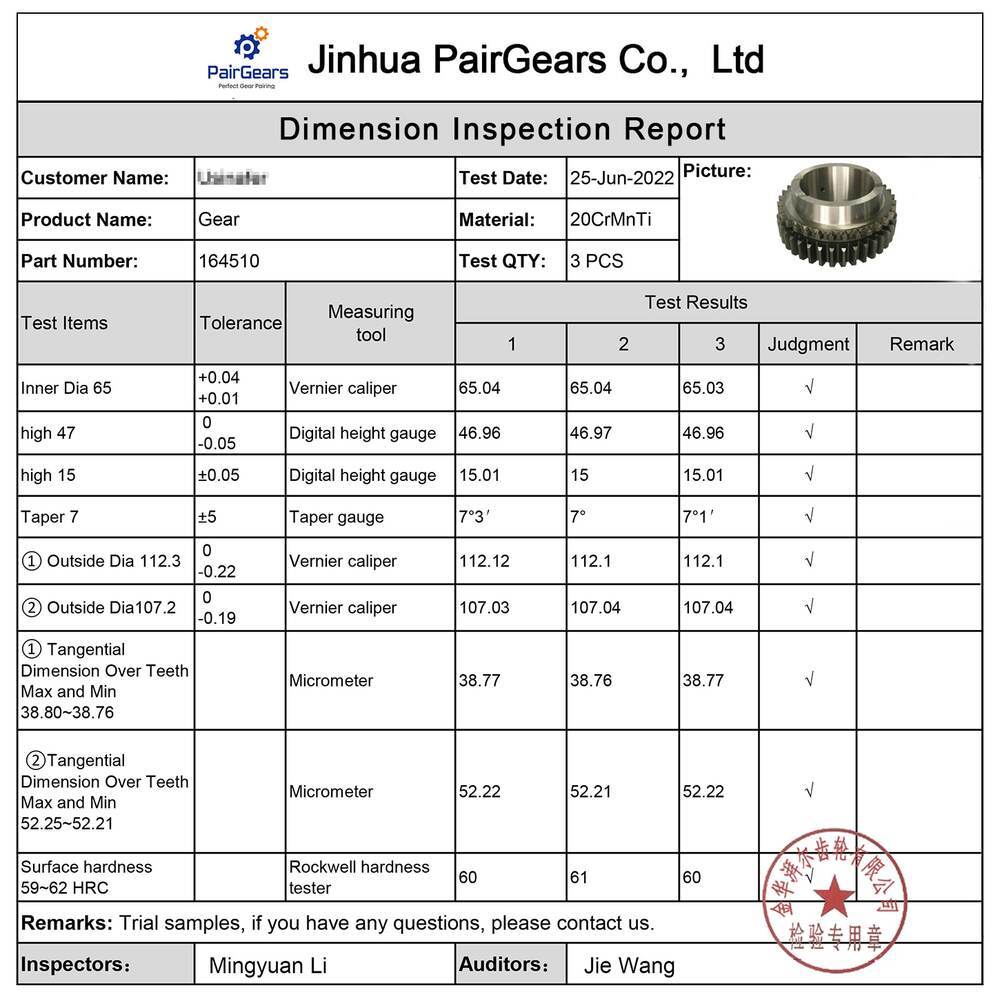
Dimension Inspection Report
Records agreed dimensional characteristics and measured results against the drawing or inspection plan.
View inspection services →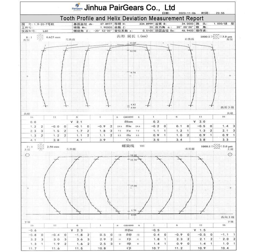
Tooth Profile & Helix Report
Shows measured gear-tooth geometry such as profile and helix or lead deviation for agreed characteristics.
View inspection services →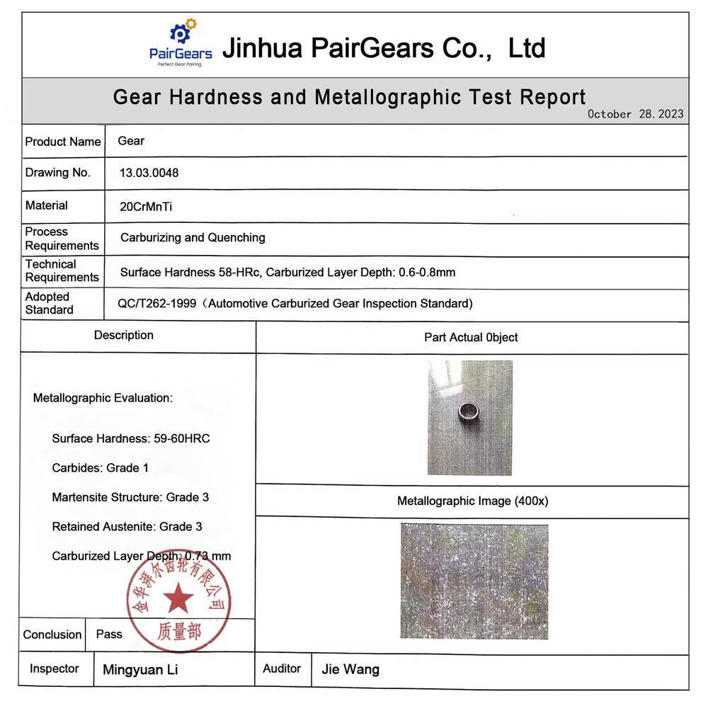
Hardness & Metallographic Report
Supports verification of selected post-heat-treatment material characteristics when included in the project plan.
View inspection services →What to send with your request
The more clearly the critical characteristics are defined, the easier it is to choose a suitable process, measuring method and report format.
Discuss Your Inspection PlanDrawing and revision
Include dimensions, tolerances, datums, gear accuracy standard and the latest drawing revision.
Material and heat treatment
State the grade, hardness, case-depth or metallographic requirements when they apply.
Application and critical features
Identify the fit, load, mating relationship and characteristics that cannot be changed.
Required documents
List the reports needed for sample approval, PPAP, incoming inspection or batch release.
Sample and batch plan
Confirm prototype quantity, sampling level and whether inspection is required per lot or per shipment.
Equipment and inspection questions
Short answers for buyers preparing a custom gear RFQ or sample-approval plan.
What equipment does PairGears use to inspect gear tooth geometry?
A gear measuring center is used for agreed tooth-geometry checks such as profile, helix or lead, pitch and runout. The exact items and standard must be defined in the inspection plan.
Can PairGears provide dimensional and gear inspection reports?
Yes, report formats can include dimensional results and gear profile or helix measurements. Availability and sampling should be confirmed before the order is released.
Is every report included with every order?
No. The report type depends on the product, order scope, drawing requirements and agreed quality documents. List required reports in the RFQ so they can be reviewed and quoted correctly.
Can a physical sample be reviewed when no production drawing is available?
A sample can support an initial measurement and feasibility review, but production still requires confirmation of critical dimensions, material, heat treatment, accuracy and application requirements.
How is the final machine and inspection route selected?
Engineering reviews the gear type, size, material, heat-treatment condition, accuracy grade, datums, batch size and required records before confirming the route.
Need to confirm whether your gear can be made and inspected?
Send the drawing, sample information and required reports. PairGears will review the process route and inspection scope before quotation.