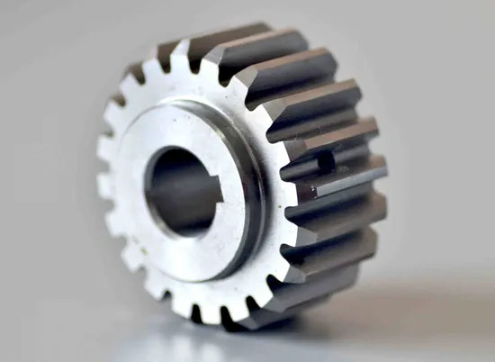
How do you calculate radial force in a spur-gear mesh?
- Share
- Issue Time
- Nov 12,2026
How do you calculate radial force in a spur-gear mesh?
For a spur gear, calculate tangential tooth force from torque and pitch diameter, then convert it through the pressure angle: Ft = 2T/d and Fr = Ft tan α. Keep the units consistent. T in N·mm with d in mm gives force in newtons. The spur mesh has no helix-generated axial thrust; shafts and bearings still carry tangential and radial forces plus application-dependent dynamic factors.
Start with torque at the gear and its pitch diameter
For a spur gear with torque T and pitch diameter d, the tangential force is Ft = 2T/d. Use the torque acting at that gear after the applicable ratio and efficiency assumptions. Keep units consistent: T in N·mm and d in mm gives Ft in newtons. Do not use outside diameter in place of pitch diameter.
The tangential component transmits torque. The radial component is the separating force along the line of centers. With pressure angle α, Fr = Ft tan α. PairGears’ spur-gear design guide explains how pressure angle and pitch diameter fit the broader design.
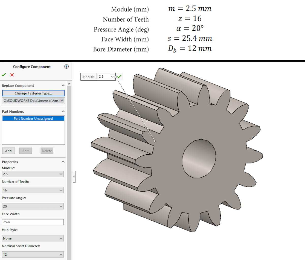
Worked example for a 20-degree spur gear
Suppose T = 100 N·m, d = 100 mm and α = 20°. Convert torque to 100,000 N·mm. Then Ft = 2 × 100,000 / 100 = 2,000 N. The radial separating force is Fr = 2,000 × tan 20° ≈ 728 N.
The vector magnitude at the mesh is √(Ft² + Fr²), about 2,129 N in this example. Keep the two components separate when resolving shaft and bearing reactions because they act in perpendicular directions. State whether reported values are nominal, factored or measured so the result is not reused under the wrong assumption.
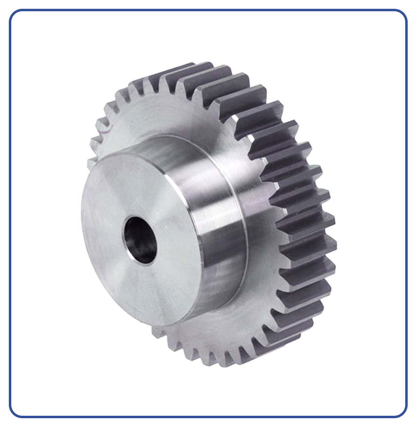
Convert gear forces into bearing reactions and design loads
A spur mesh does not create helix-related axial thrust, but the shaft still carries tangential and radial loads. Bearing reactions depend on the gear position, bearing span, overhang and any other loads; distribute each force component with a free-body diagram, then combine the bearing reactions vectorially.
Nominal equations are the starting point, not the complete service load. Apply the project’s approved factors for shock, duty, accuracy, dynamic behavior and reliability, and check shaft deflection, bearing life and housing stiffness. Helical and bevel gears require additional axial-force equations, so do not reuse this spur-gear formula for those meshes.