How should a plastic gear be fastened to a shaft?
- Share
- Issue Time
- Oct 24,2026
How should a plastic gear be fastened to a shaft?
Fasten a plastic gear using a connection designed for its resin, hub geometry and duty. A key, shaped bore or engineered metal hub may be suitable, but a mounting method used on a steel gear is not automatically suitable for plastic. Check torque transfer, local stress, temperature, moisture effects and axial retention before approving the assembly.
Start with the actual gear and bore design
Identify the manufacturer, part drawing, resin grade and whether the hub is entirely plastic or contains a metal insert. A bore diameter alone does not identify the permitted mounting method. For a purchased molded gear, follow the mounting instructions for that exact part before adding a keyway, cross-hole or set screw.
A shaped bore can provide a defined torque path, while a round bore needs another specified connection. Treat the shaft fit and axial location as drawing requirements rather than relying on the teeth to keep the gear in position.
Check the plastic hub as well as the teeth
A keyway loads the sides of the plastic hub. Review its contact stress, effective length, corner radii and remaining material, especially with shocks or reversals. Where a plastic hub is unsuitable, an engineered metal hub can provide the shaft connection; its attachment to the plastic still needs its own capacity check.
For example, a keyed metal insert introduces two interfaces: shaft-to-insert and insert-to-plastic. A satisfactory key calculation at the first interface does not prove that the second will resist slipping or loosening. Do not transfer steel interference-fit values directly to a plastic bore.
Specify the condition in which the fit is accepted
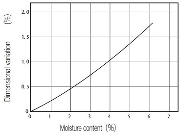
Plastic dimensions can change with temperature and moisture; the size of that change depends on the resin and condition. Specify the assembly temperature, material conditioning and operating environment. A room-temperature fit check alone may not describe the running condition.
Define axial retention separately, then verify assembled runout and the connection under the agreed duty. Send both the gear and shaft drawings with peak torque, reversals, speed and environment. The PairGears custom cylindrical gear service provides a route for project review; the mounting design and manufacturing process must be agreed for the specific part.