What does a JIS Type 3 worm tooth profile mean?
- Share
- Issue Time
- Oct 20,2026
What does a JIS Type 3 worm tooth profile mean?
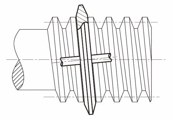
JIS Type 3 describes a worm tooth-profile form produced with a milling cutter or grinding wheel that has a trapezoidal profile in the tool plane. It is also called the K form in the classification described by KHK. Type 3 identifies the profile family; it does not mean accuracy grade 3 or a three-start worm.
Read Type 3 as a tooth-form designation
The defining trapezoidal shape belongs to the cutter or grinding wheel in its tool plane. Do not interpret that description as a requirement for a straight-sided trapezoid in every section through the finished worm.
On a drawing, keep tooth form, accuracy standard and number of starts in separate fields. For example, “Type 3” and “two starts” can describe the same worm without contradiction: one identifies the profile family and the other counts the helical threads. Confirm the exact standard and edition required by the drawing.
Specify the remaining worm geometry
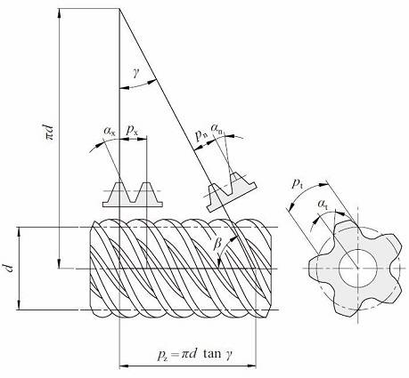
A profile designation alone leaves the size and mesh undefined. State the module and its axial or normal convention, pressure angle and its convention, number of starts, reference diameter, lead or lead angle, hand, face length and shaft details. Supply the wheel data and intended center distance with the worm drawing.
The adjacent diagram distinguishes normal and axial quantities. Values in those two planes are not interchangeable without the correct conversion. The PairGears worm gear manufacturing guide provides further context for a paired manufacturing specification.
Match the wheel and the inspection requirement
Have the supplier verify that the wheel’s generated tooth geometry matches the specified worm, with the intended mounting dimensions and backlash. Matching a nominal module and tooth counts alone does not establish a compatible replacement set.
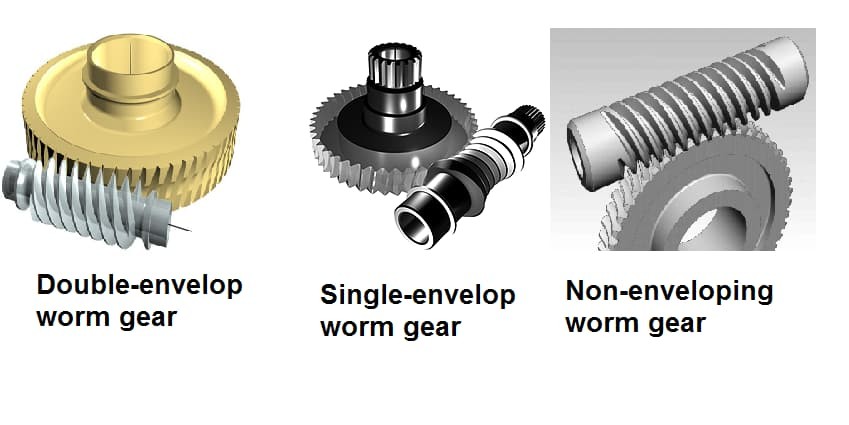
Envelope geometry is another separate design choice, illustrated here. Neither a tooth-form label nor an envelope description guarantees efficiency, self-locking or load capacity. For a replacement, send both drawings or identify the existing matched set, and agree how profile, dimensions and functional contact will be checked.