How do I specify profile shift for crossed-helical screw gears?
- Share
- Issue Time
- Oct 14,2026
How do I specify profile shift for crossed-helical screw gears?
Specify profile shift as part of the complete crossed-helical gear-pair design, with a stated coefficient convention for each member. Provide normal module, normal pressure angle, tooth counts, helix angles and hands, shaft angle and operating center distance. A designer must check the resulting working geometry and tooth contact. Moving an existing gear along its shaft does not create profile shift.
Separate tooth modification from assembly movement
In this context, screw gears are crossed-helical gears operating on nonparallel, nonintersecting shafts. Profile shift describes a change in generated tooth geometry relative to the reference tooth system. It is specified during design and manufacture.
If “shifting” means repositioning a finished gear on its shaft, describe that as an axial mounting adjustment. It does not change the gear’s manufactured profile-shift coefficient. Keeping the two meanings separate helps the supplier interpret the drawing correctly.
Submit the pair geometry and the design objective
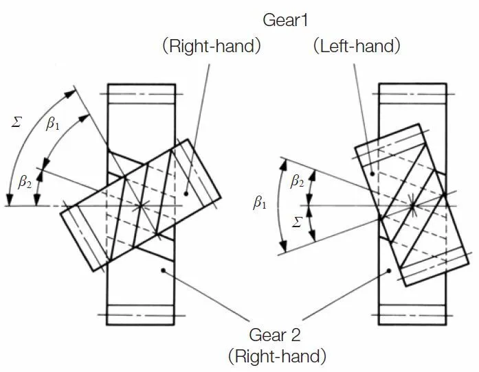
Give the normal module and pressure angle common to the tooth system, each tooth count, reference helix angle and hand, required shaft angle, center distance, face widths and available envelope. State whether coefficients use a normal-system convention; do not mix normal and transverse data.
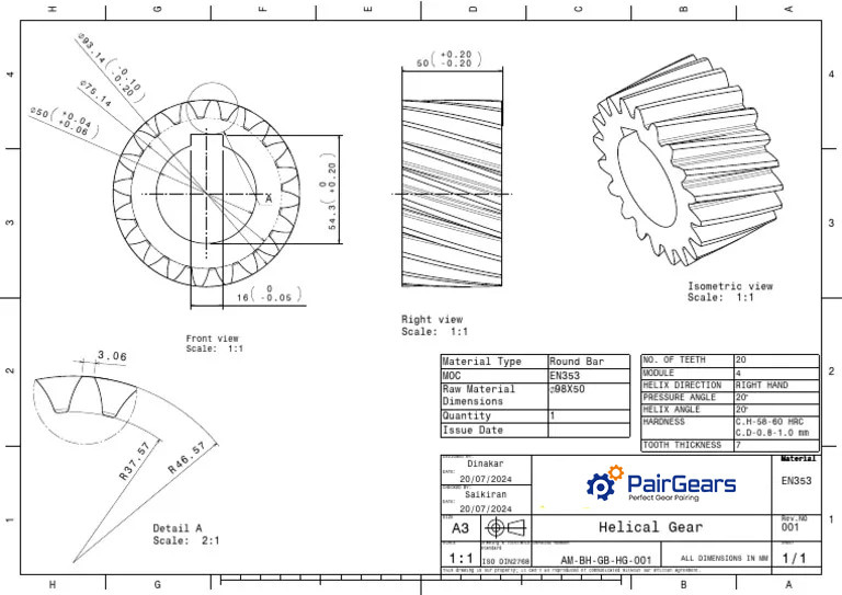
For example, if a replacement must fit an existing housing, provide its measured center distance and shaft angle together with both gears’ drawings. Ask for a compatible pair calculation instead of selecting one gear’s shift coefficient in isolation. The PairGears custom gear drawing checklist helps organize the required drawing information.
Recalculate the mesh before releasing the drawing
A shifted crossed-helical pair needs a check of its working pitch diameters and working helix angles. Do not automatically substitute the reference helix angles into a shaft-angle relationship derived for an unshifted pair. The helix-hand arrangement also matters.
Check tooth thickness, tip and root clearance, interference, backlash and contact at the intended mounting dimensions. Evaluate load, speed, lubrication and bearing thrust separately. Crossed-helical contact and sliding limit the application; a geometrically possible profile shift alone does not establish adequate life or load capacity.