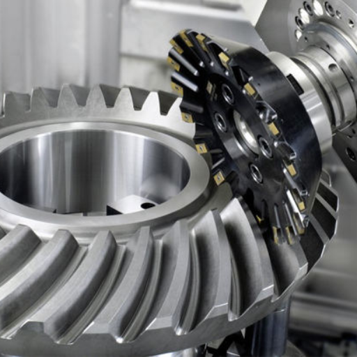
How do change gears work in a hobbing machine?
- Share
- Issue Time
- Oct 7,2026
How do change gears work in a hobbing machine?
On a mechanical hobbing machine, change gears set the required relationship between hob rotation and workpiece rotation. The indexing train depends on the desired tooth count, hob starts and machine constant. Other trains may control feed or helical compensation. Use the manual for the exact machine; the change-gear ratio is not necessarily the same as the hob-to-workpiece speed ratio.
Separate the cutting relationship from the gear train
For basic spur-gear generation, the magnitude of workpiece speed divided by hob speed is k / z, where k is the number of hob starts and z is the workpiece tooth count. A single-start hob making a 40-tooth gear therefore requires one workpiece revolution per 40 hob revolutions.
The machine already contains fixed gearing. Its index constant accounts for that gearing when selecting the removable change gears. A drawing of the cutting motion is not, by itself, a mounting chart for those gears.
Apply the machine constant and ratio convention
Suppose a manual defines driver-to-driven tooth-product ratio as C × k / z. With C = 24, k = 1 and z = 40, the required ratio is 0.6. An arithmetic example is (30 × 40) / (50 × 40) = 0.6. This does not establish that those gears fit the machine or that the shaft order and direction are correct.
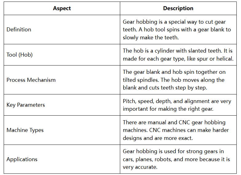
Confirm the manual's ratio convention, available gears, shaft spacing and rotation direction. A different machine may use a reciprocal convention or different fixed gearing. The PairGears hobbing overview provides process context, not a machine-specific setup sheet.
Keep feed and helical compensation coordinated
Feed settings determine travel through the workpiece. Helical cutting also needs the appropriate extra rotational relationship with axial travel. Differential and non-differential hobbers implement this differently; changing one train independently can spoil the helix. CNC machines may synchronize axes electronically.
Hobbing continuously coordinates cutter and work rotation. Conventional form milling can cut one space and then index to the next, so its dividing-head instructions are not interchangeable with a hobber setup. Before production, verify the specified setup and inspect a trial part for tooth count, pitch and helix where applicable.