What is lead crowning on a gear tooth?
- Share
- Issue Time
- Oct 6,2026
What is lead crowning on a gear tooth?
Lead crowning is a small, intentional convex modification of a gear tooth flank across its face width. The flank is relieved toward the ends relative to the middle, helping limit edge contact when shafts or supports deflect or misalign. It differs from tip relief along the tooth profile. The crown amount must suit the actual load and alignment; more crowning is not automatically better.
Distinguish lead modification from profile relief
Lead crowning changes the flank across the tooth width. Profile relief changes the tooth in the root-to-tip direction. End relief is another lead-direction modification concentrated near the ends; it is not necessarily the same continuous crown shape.
State the direction, shape, amount, reference and tolerances on the drawing. A note saying only 'crowned teeth' can leave the intended geometry ambiguous.
Choose the crown for the operating condition
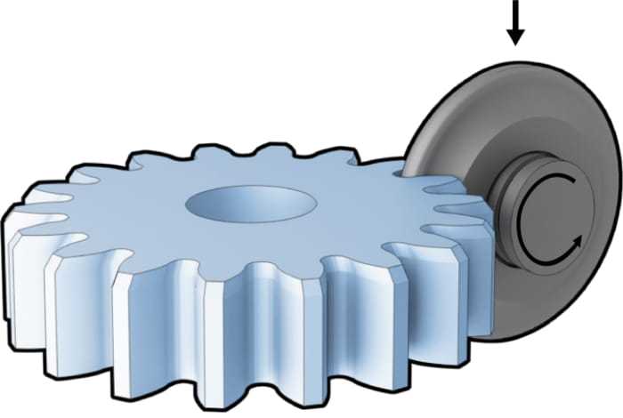
A small angular misalignment can shift contact toward one end of the face. A suitable crown can reduce that sensitivity. Excessive crowning can concentrate load on too little face width and raise local contact stress, so the correction should be evaluated across the intended load range.
For example, compare the contact predicted at light load and rated load using the expected shaft and housing deflections. Do not copy a crown value from an unrelated gear or treat crowning as a guaranteed noise cure.
Verify the specified surface and the working contact
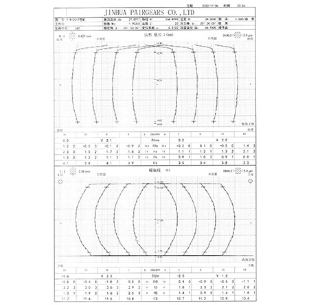
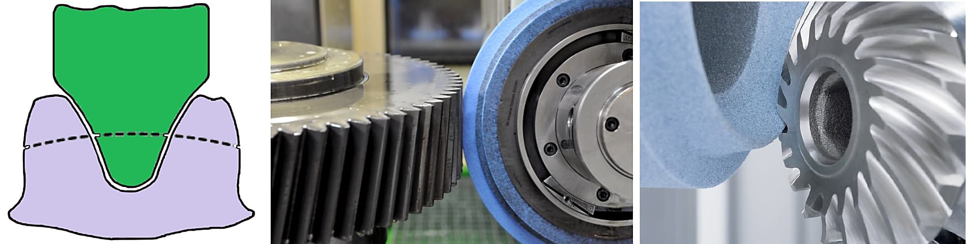
Agree the lead measurement locations, evaluation range and permitted deviation from the specified modification. Review the inspection trace against that target, not against an unmodified straight flank. Contact checks should use the actual mating part and defined assembly and load conditions.
The PairGears gear-inspection guide explains why measured tooth data must connect to drawing requirements. A report example is not proof that a particular crown or loaded contact condition has been achieved.