What is gear tooth thickness, and where is it measured?
- Share
- Issue Time
- Sep 24,2026
What is gear tooth thickness, and where is it measured?
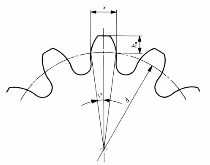
Gear tooth thickness is the distance between the two flanks of one tooth at a specified location and in a specified plane. Circular tooth thickness is measured as an arc on a stated circle; chordal thickness is a straight-line distance. The reference circle is a common basis, but a drawing must identify the definition, measurement method and allowable limits.
Name the circle and the measurement plane
For an ideal, unshifted spur gear with no tooth-thickness reduction for backlash, reference-circle circular thickness is half the circular pitch: s = pi × m / 2. At module 2, that theoretical value is about 3.142 mm.
This is not automatically a finished-part acceptance value. Profile shift and specified thinning change the target. Chordal thickness requires the corresponding chord and measuring height; helical gears also require the normal or transverse plane to be identified.
Separate tooth thickness from the inspection reading
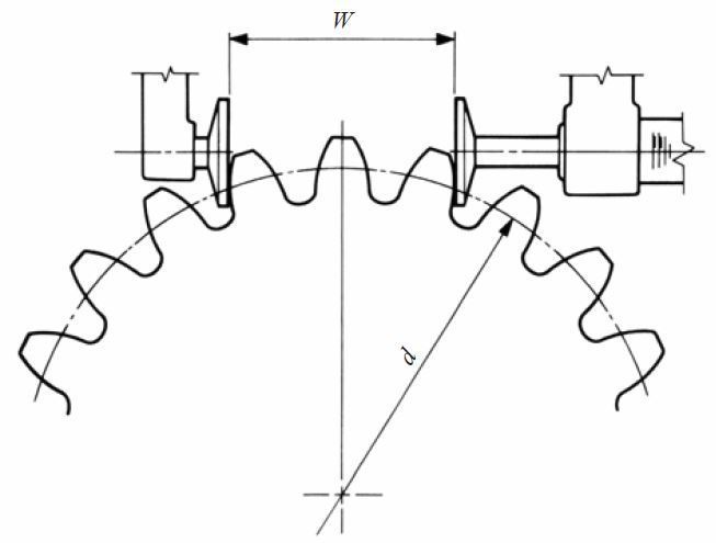
Span measurement over a defined number of teeth and measurements over pins or balls can be used to assess tooth thickness. Their readings include the geometry of the method; a span value is not the thickness of one tooth.
The PairGears tooth-thickness guide compares practical methods. Record the span tooth count or pin size and the correct nominal value and tolerance.
Use the result with the mating-gear requirements
Tooth thickness contributes to backlash, but the assembled clearance also depends on the mating gear and operating center distance. A passing thickness reading does not by itself prove that the pair has the required backlash.
For a replacement gear, use the drawing-defined measurement rather than copying a worn tooth. Check profile, lead, pitch and runout separately where required; tooth-thickness compliance does not establish the complete accuracy grade.