What is the gear hobbing process?
- Share
- Issue Time
- Sep 17,2026
What is the gear hobbing process?
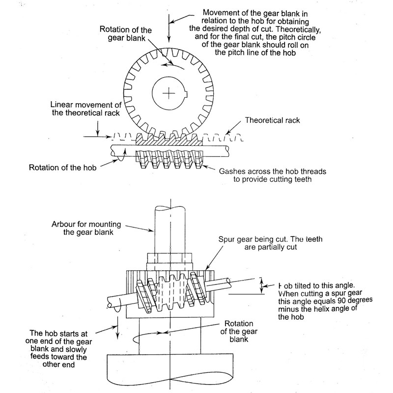
Gear hobbing generates teeth by rotating a threaded cutting tool, called a hob, in a controlled relationship with a gear blank. As the cutter feeds across the face width, successive cuts form the tooth spaces. It is widely used for external spur and helical gears, with later heat treatment and finishing selected to meet the drawing.
How the teeth are generated
The hob and workpiece rotate together throughout cutting. This generating motion progressively forms the tooth profile, rather than milling one finished space and then indexing to the next. The hob must match the specified pitch and tooth system.
For a simple spur-gear example, a single-start hob makes 40 revolutions while a 40-tooth blank makes one revolution. This illustrates indexing only; it does not specify cutting speed, feed or a production cycle time.
What happens on the machine?
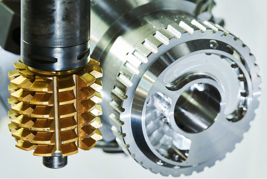
- Prepare and locate the blank: establish the bore, faces and workholding datums.
- Set the cutter: confirm its geometry, alignment and available approach clearance.
- Generate the teeth: coordinate rotation, cutting depth and feed across the face.
- Check the result: deburr and inspect the features required by the drawing before downstream operations.
Where does hobbing need another process?
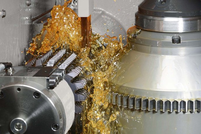
Conventional hobbing needs external cutter access. Internal teeth and shoulders that block the hob may require another route. Hardening can change tooth geometry, so an acceptable hobbed part does not by itself establish final accuracy.
PairGears’ hobbing guide gives the process context. Confirm any shaving before hardening or grinding after hardening as part of the agreed route.