What assembly errors are allowable for a worm gear pair?
- Share
- Issue Time
- Aug 17,2026
Worm gear assembly errors: use the approved pair, not a generic limit
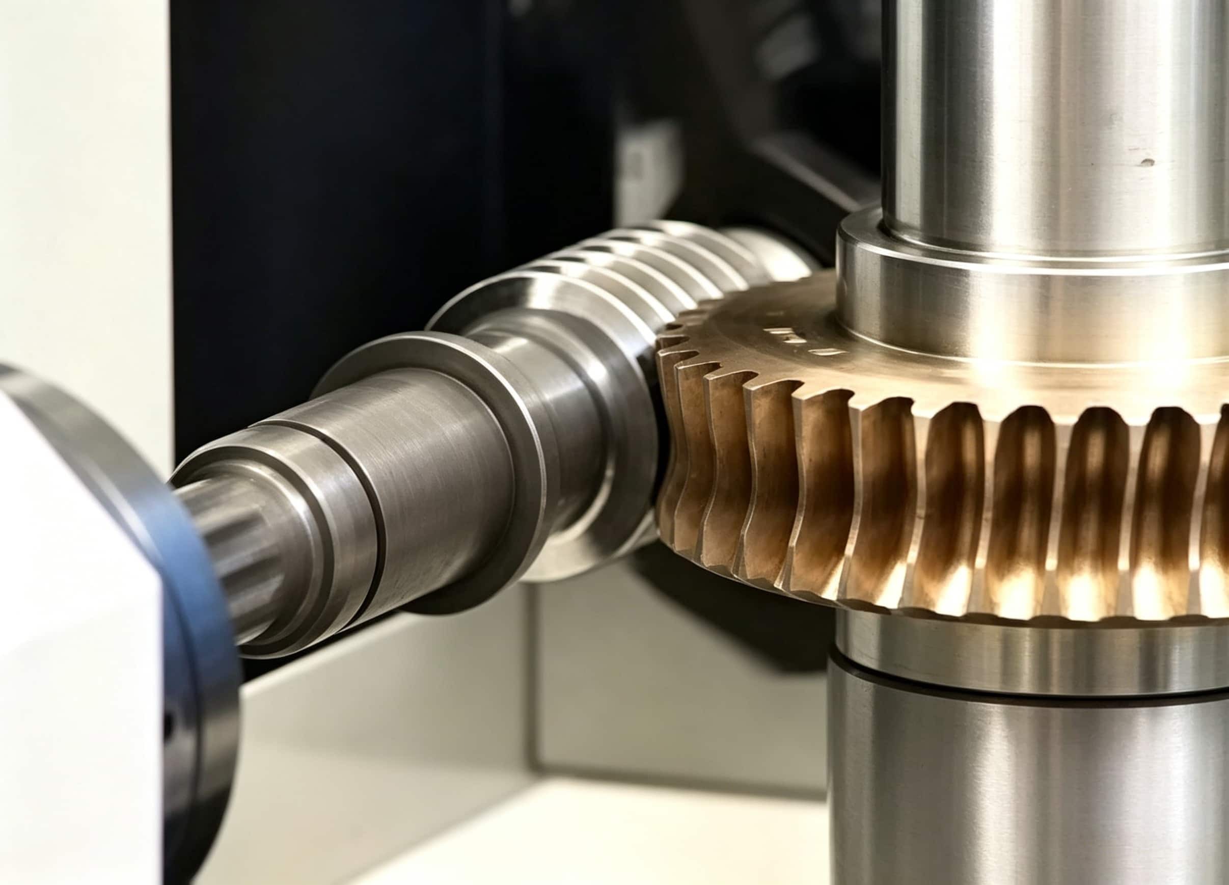
There is no universal allowable misalignment for a worm gear pair. The acceptable shaft angle, center distance and wheel position depend on the approved geometry, tooth contact target, backlash, bearing arrangement, housing stiffness, lubrication and duty cycle. PairGears should review a custom or replacement pair against its drawing and assembly conditions; a stock-catalog tolerance is not automatically transferable.
What to check before accepting the setup
- Lock down the pair: identify the worm and wheel as a matched set, including starts, tooth count, lead angle and hand.
- Control the locating features: use the drawing datums for shaft angle, center distance and wheel position; avoid using a worn tooth flank as a reference.
- Verify function, not one dimension: record backlash convention, contact pattern, runout, bearing setting and expected temperature.
- Check service conditions: sliding contact makes lubricant, temperature and load important when deciding whether a pattern or clearance is acceptable.
For the required inputs, see the PairGears worm-gear manufacturing guide.
Example: make the review measurable
A supplier may publish values for a particular stock family, but a custom pair with different lead angle, face width or housing support requires its own target. Submit the gear drawings, housing layout, bearing locations, backlash requirement, lubricant and duty cycle; then measure and record the accepted contact pattern at that defined setup.