Is a 3D Model Enough for a Spur Gear Manufacturer?
- Share
- publisher
- Jessica
- Issue Time
- Aug 3,2026
Summary
Learn whether a 3D model is enough for spur gear manufacturing and which tooth data, tolerances, materials, and inspection details buyers must confirm.
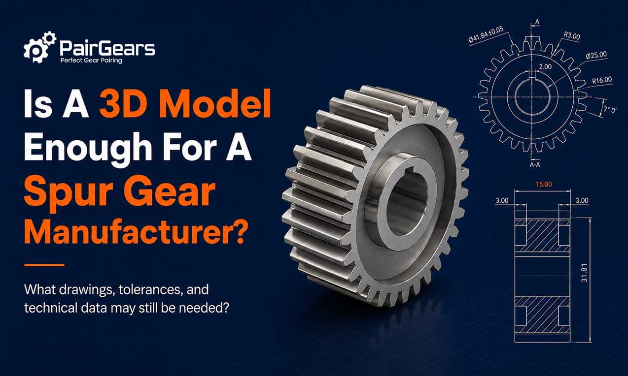
Many spur gear projects begin with a STEP, IGES, or another 3D CAD file. For a precision gear manufacturer, the model is useful for reviewing part geometry, structure, and initial manufacturability.
However, spur gear manufacturing requires more than nominal geometry. A standard 3D model may not fully define the material, heat treatment, gear quality grade, critical tolerances, datums, and acceptance criteria. Whether a 3D model is enough depends on the stage of the project.
Quick Answer
A 3D model can support an initial review, but it is rarely enough for production.
The spur gear manufacturer must also confirm the tooth data, tolerances, material, heat treatment, quality grade, and inspection requirements.
What Can a Spur Gear Manufacturer Confirm from a 3D Model?
A complete and correctly scaled 3D model can help the manufacturer review:
This information supports early technical discussions for custom precision gears and helps the manufacturer select a suitable process, such as hobbing, shaping, shaving, or grinding. However, a standard 3D model usually shows only nominal geometry and does not define critical dimensions or acceptable manufacturing variation.
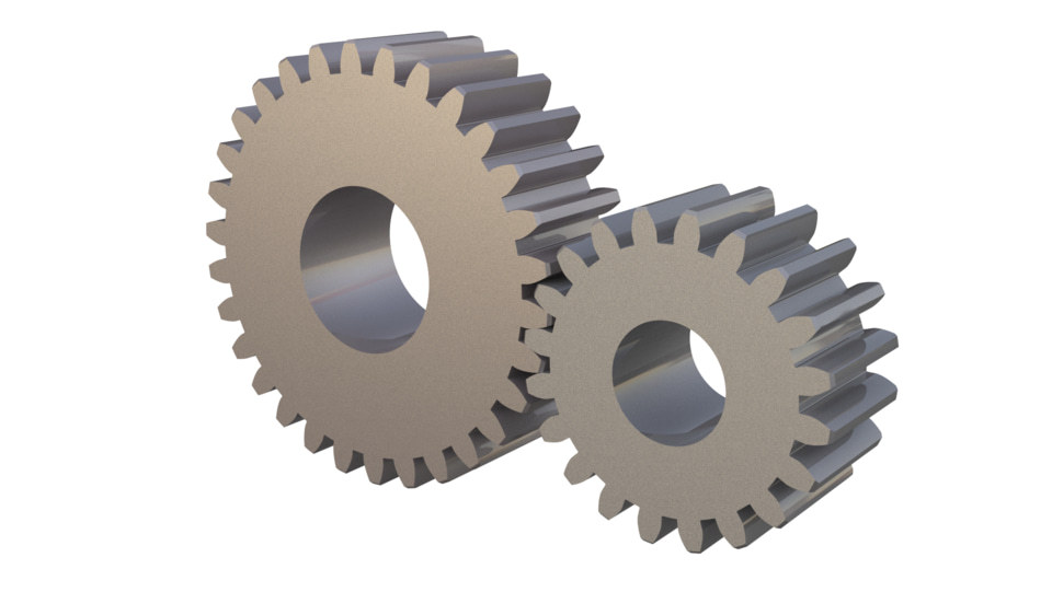
Why a Spur Gear Manufacturer Still Needs Technical Details
The same 3D geometry may be used with different materials, quality grades, and operating requirements. A spur gear used in a low-speed auxiliary mechanism may require a different manufacturing and inspection plan from one used in a heavy-duty transmission or high-speed machine.
| Technical Information | Can a Standard 3D Model Fully Define It? | How to Confirm It Before Production |
|---|---|---|
| Tooth count and overall geometry | Usually | Check the model revision |
| Module or diametral pitch | Sometimes calculated from the model | State it in the drawing or specification |
| Pressure angle | Not always clear or reliable | Specify the design value |
| Profile shift coefficient | Usually unclear | Provide the gear data or design calculation |
| Tooth thickness or backlash | Usually incomplete | Confirm it with the mating gear and center distance |
| Gear quality grade | Cannot be determined from geometry | Specify the ISO, DIN, or AGMA grade |
| Material | May not be included | Provide the material grade or performance requirements |
| Heat treatment and hardness | Usually unavailable | Define the process, hardness, and treated area |
| Dimensional tolerances and datums | Usually incomplete | Provide a 2D drawing or controlled specification |
| Profile, lead, and runout tolerances | Cannot be confirmed from nominal geometry | Define the inspection items and limits |
| Surface roughness | Usually unclear | Mark the required surfaces |
| Inspection documents | Cannot be shown by geometry | Agree on the required reports and certificates |
Do not treat calculated values as approved design data: Calculating tooth data from the model may lead to different interpretations. For example, a manufacturer may estimate the module and pressure angle from the tooth geometry, but those estimates do not confirm the original design requirements.
When Is a 3D Model Enough for the Current Project Stage?
The answer depends on what the buyer wants to achieve at the current project stage.
| Project Stage | May a 3D Model Be Enough? | What Else Should Be Confirmed? |
|---|---|---|
| Initial feasibility review | Usually | Gear type, approximate size, and quantity |
| Budget quotation | Possibly | Material, heat treatment, quality grade, and inspection scope |
| Prototype manufacturing | Usually not | Tooth data, tolerances, datums, and acceptance criteria |
| Mass production | A standard model alone is not recommended | Controlled revisions, approval records, and complete inspection criteria |
For a budget quotation, the manufacturer may estimate the price based on the model and clearly stated assumptions. Before prototype or mass production, both parties should confirm all open technical details and convert these assumptions into controlled manufacturing requirements, as any changes may affect the final price.
Which Spur Gear Parameters Should Buyers Confirm?
A spur gear may appear simple, but tooth count and outside diameter alone do not fully define its tooth geometry. Buyers should confirm the following information before production.
Basic Tooth Geometry
- Module or diametral pitch
- Number of teeth
- Pressure angle
- Face width
- Profile shift coefficient, if applicable
- Tooth thickness, measurement over pins, or another tooth thickness control method
Assembly Information
- Mating gear data
- Design center distance
- Target backlash
- Bore, keyway, spline, and fit requirements
- Datum relationships between the bore, faces, and gear teeth
Performance and Quality Requirements
- Torque, speed, and duty cycle
- Shock loads or frequent reversing operation
- Material, heat treatment, hardness, and case depth requirements
- Gear quality standard and grade
- Profile, lead, pitch, runout, or noise requirements
These details affect the machining route, equipment selection, inspection method, quotation, and lead time. For early RFQ preparation, buyers can also organize the same information used in a custom gear quote.
Can a 3D Model Replace a 2D Spur Gear Drawing?
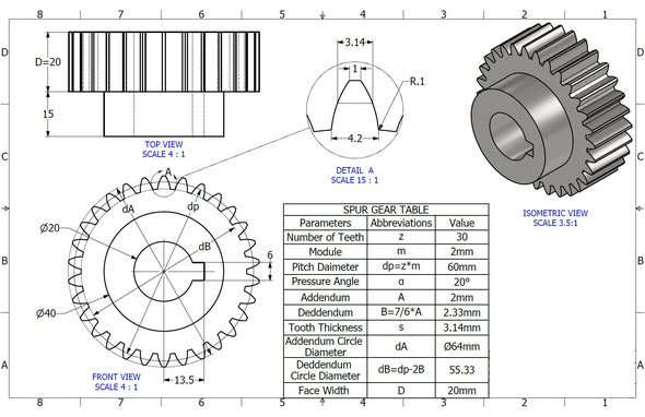
A 2D drawing remains a clear way to define tolerances, datums, materials, heat treatment, and inspection requirements. A controlled 3D model may replace it if it contains all necessary manufacturing information and the manufacturer can read the embedded data and verify the correct revision.
File control matters more than the file format. Whether the project uses a 2D drawing or a controlled 3D model, both parties should define:
Approved File
The current approved filename and revision
File Priority
Which file takes precedence if the drawing and model conflict
Critical Characteristics
Which dimensions are critical characteristics
Approval Responsibility
Who approves the manufacturing documents
Change Control
How design changes will be recorded and communicated
Revision control is essential: Without revision control, production teams may use an outdated file even when the latest model is correct.
What Happens If the 2D Drawing and 3D Model Conflict?
Differences between a drawing and a model require clarification before production. The manufacturer should not select one version and continue without the buyer's approval.
Common conflicts include:
The manufacturer should list the differences and request written confirmation from the buyer. Both parties can then approve the file revision used for the quotation, prototype, or mass production.
How Should a Spur Gear Be Inspected?
Drawings and models guide both manufacturing and inspection. The inspection plan should match the part tolerances and operating requirements.
A spur gear inspection may cover:
Bore, Face, and Keyway
Bore, face, and keyway dimensions
Radial Runout
Gear rim radial runout
Gear Deviations
Profile, lead, and pitch deviations
Tooth Thickness
Tooth thickness or measurement over pins
Material and Heat Treatment
Material, hardness, and heat treatment results
Assembly Dimensions
Assembly dimensions related to the mating gear
For projects requiring inspection reports, both parties should confirm the scope of gear inspection before shipment during quotation. The project requirements should define the inspection equipment, measurement method, sampling plan, acceptance limits, and required reports, because an inspection report cannot verify criteria that the buyer and manufacturer have not agreed on.
How PairGears Reviews 3D Spur Gear Models
PairGears can begin a project review using a 2D drawing, a 3D CAD model, or a physical sample. For a spur gear project that begins with only a 3D model, the review may include these steps:
Check the File
Check whether the model is complete and readable, then confirm its revision.
Review the Structure
Review the gear structure, major dimensions, and possible machining route.
Confirm Tooth Data
Confirm the module, tooth count, pressure angle, tooth thickness, and assembly data.
Review Requirements
Review the material, heat treatment, quality grade, tolerances, and inspection requirements.
List Open Points
List missing information, file conflicts, and quotation assumptions.
Approve the Basis
Approve the manufacturing basis before prototype or mass production begins.
When the project moves from file review to production planning, the custom gear manufacturing process should connect the approved files, application requirements, material, prototype approval, and inspection scope.
Starting with Only a 3D Model?
Send the available model, tooth data, material requirements, application information, and project stage for an initial review.
Buyer Checklist Before Sending a 3D Model
Before sending the files, check whether:
File Opens
The STEP, IGES, or other model opens correctly
Latest Revision
The model is the latest approved revision
Tooth Parameters
A separate drawing or data sheet defines the tooth parameters
Material and Heat Treatment
The material and heat treatment requirements are clear
Critical Requirements
Critical dimensions, tolerances, and datums are marked
Quality and Inspection
The gear quality grade and inspection items are defined
No File Conflict
The 2D drawing and 3D model contain no unresolved conflicts
Application Package
The file package includes the application, load, speed, and required quantity
If some information is still under review, buyers can send the model first. They should state whether the project is at the concept, budget, prototype, or production stage.
FAQ
Can I get a spur gear quotation with only a STEP file?
A STEP file may be enough for an initial review or budget quotation. If the material, heat treatment, gear quality, quantity, or inspection scope is unclear, the manufacturer should list the assumptions used in the quotation.
Can a manufacturer identify the module and pressure angle from a 3D model?
Some models allow the manufacturer to measure or calculate these parameters. However, calculated values should not replace design approval. The buyer or designer should approve the final gear data.
Can a 3D model define the gear quality grade?
A standard solid model shows nominal geometry. It does not define the allowable profile, lead, pitch, or runout deviations after manufacturing.
What should buyers do if the drawing and model do not match?
The manufacturer should pause the quotation review or production and list the differences. The buyer should then confirm the approved file and revision in writing.
Can a manufacturer produce a prototype without a 2D drawing?
The manufacturer can review the project, but both parties should approve a controlled manufacturing definition before machining begins. This may be a confirmed manufacturing drawing, a complete technical specification, or an approved model containing all required manufacturing information.
Send Your Spur Gear Model for Review
A 3D model can help a spur gear project move into technical review quickly. Whether it is sufficient depends on the project stage and the completeness of the technical information.
Have a Spur Gear 3D Model?
Contact us to send your 3D model, available 2D drawings, tooth data, material requirements, and application information. We will review the file package and identify what you need to confirm before quotation, prototype manufacturing, or mass production.