How to Read Bevel Gear Contact Patterns
- Share
- publisher
- PairGears
- Issue Time
- Aug 17,2026
Summary
Learn how to read bevel gear contact patterns and what buyers should check, including mounting distance, backlash, load position and matched pairs.
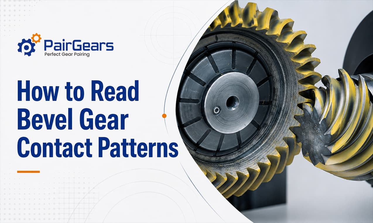
A bevel gear contact pattern helps show how a gear pair is meshing under a defined checking condition. Even when both gears meet their individual dimensional requirements, the assembled set can still run poorly if contact position, backlash, or mounting setup is wrong.
At PairGears, contact patterns are reviewed together with mounting distance, backlash, rotation direction, bearing support, and mating-part condition. This is especially important in replacement and reverse-engineering projects, where old wear marks may not represent the original design.
What Does a Bevel Gear Contact Pattern Show?
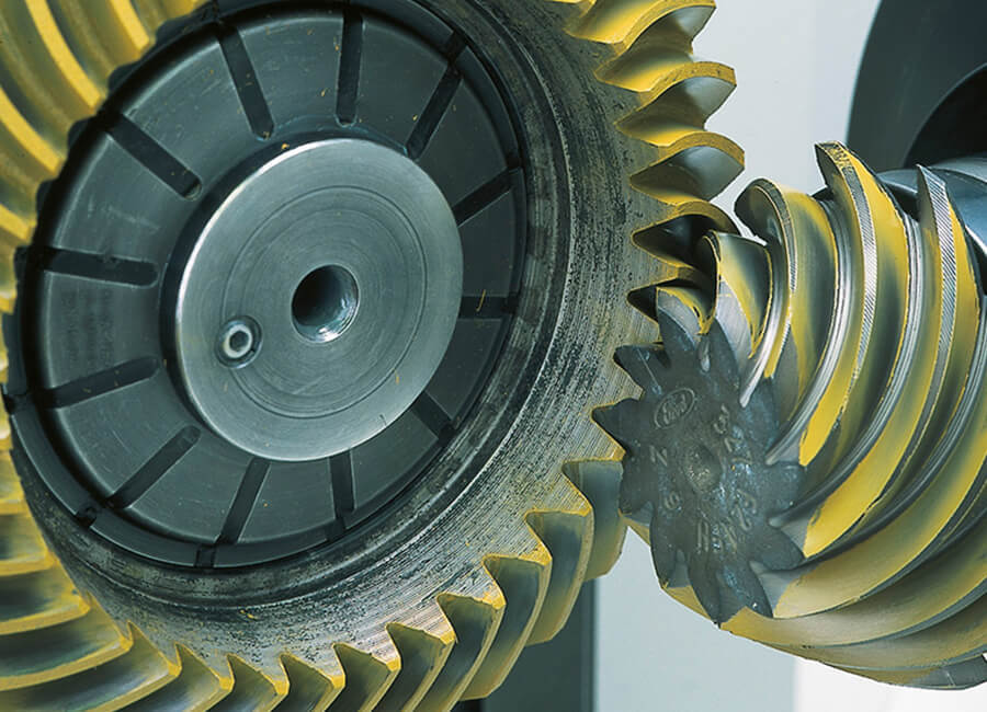
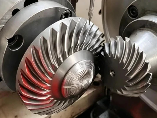
A bevel gear contact pattern shows where the tooth flanks touch when the pair is checked with marking compound, light load, or another defined setup. Its position, size, and shape help indicate whether the pair is contacting as intended.
It is not a stand-alone pass/fail result. Changes in mounting distance and backlash, bearing support, or the checking method can move or reshape the mark, so one photo cannot confirm the whole gear set.
Key point: Contact pattern is meaningful only when the checking condition and mounting setup are known.
Why Contact Pattern Matters for Bevel Gear Sets
Many precision bevel gear applications are evaluated as sets, especially spiral bevel gears, hypoid gears, and gear and pinion sets. Contact and backlash depend on both members and their mounting position, so a shifted pattern can point to setup or matching issues before the set goes into service.
In replacement gear projects, the pattern can also help compare a new gear with the existing mating part. If only one old gear or OEM number is available, mating-gear data, installation position, wear marks, and running feedback become more useful than appearance alone.
What Should You Look for in a Bevel Gear Contact Pattern
The mark itself is only part of the story. Start with its position, size, tooth side, and distance from the edges.
Contact Position
The target contact area depends on the gear design, tooth side, checking method, and specified load. Compare the observed mark with the drawing or agreed inspection criteria; a strong toe/heel bias or unintended edge contact calls for a setup review.
Contact Length and Width
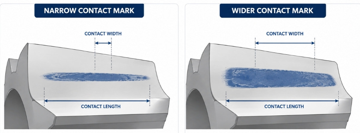
A very narrow pattern can mean limited contact under the checking condition. A broad or heavy-looking mark does not automatically mean overload; backlash, setup load, marking compound, and the checking method can all change its appearance. Judge it against the specified condition, not by darkness alone.
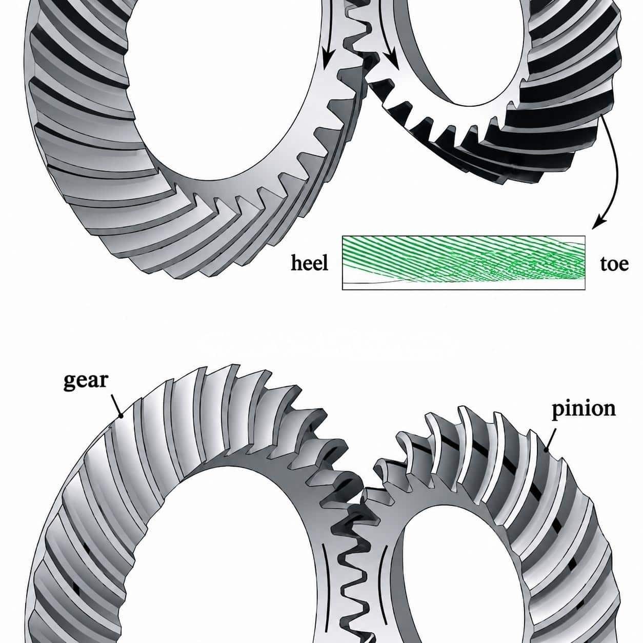
Toe and Heel Contact
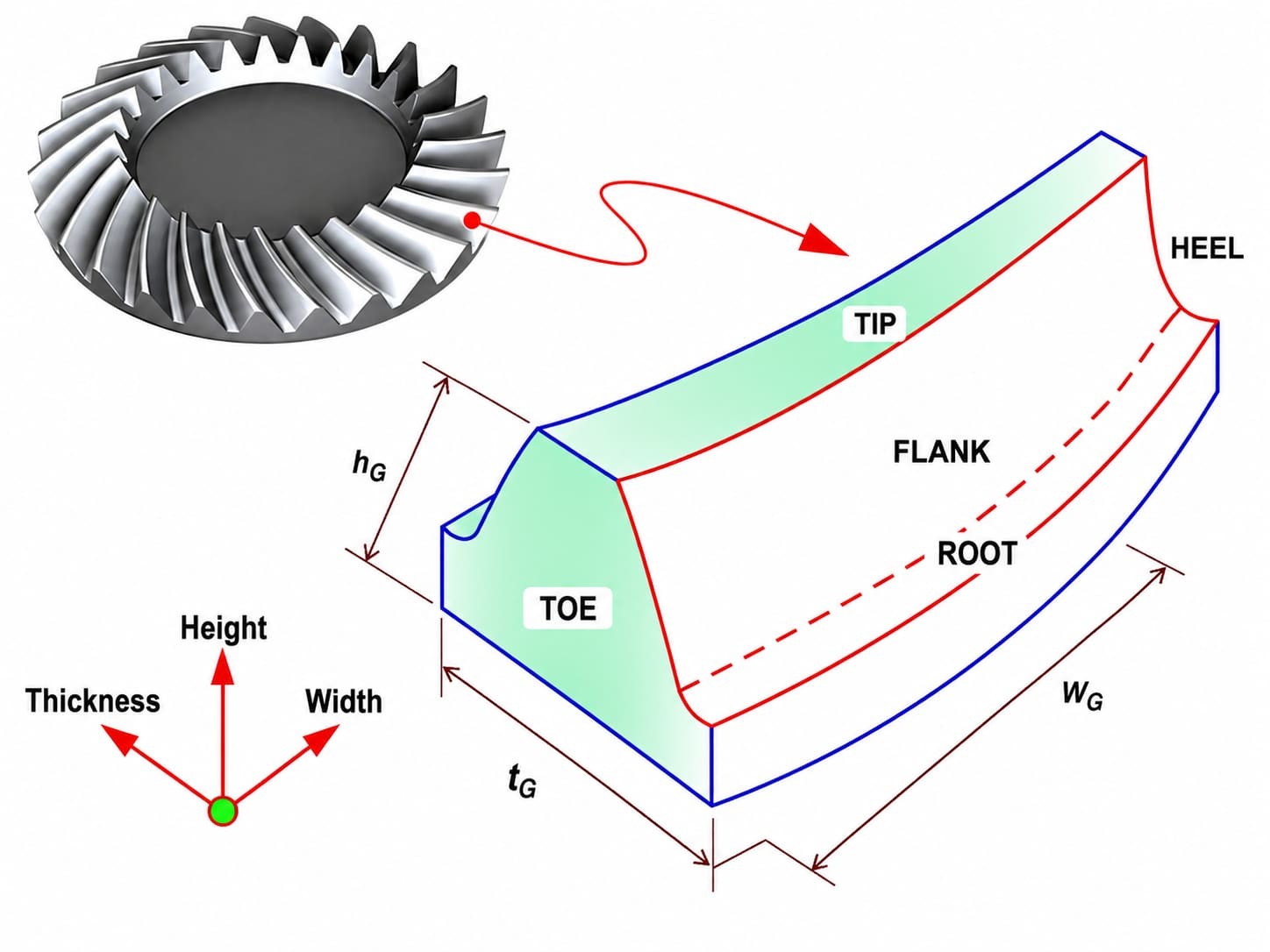
The toe is the small end of the tooth and the heel is the large end. A clear bias toward either end is not a diagnosis by itself; review mounting distance, backlash, bearing support, and assembly position before changing the gear.
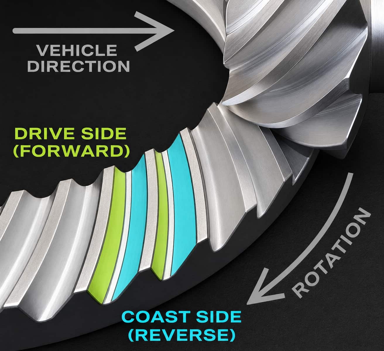
Drive Side and Coast Side
First identify whether the mark is on the drive or coast flank. Because load direction can change the pattern, confirm the rotation direction and checking method before comparing the two sides.
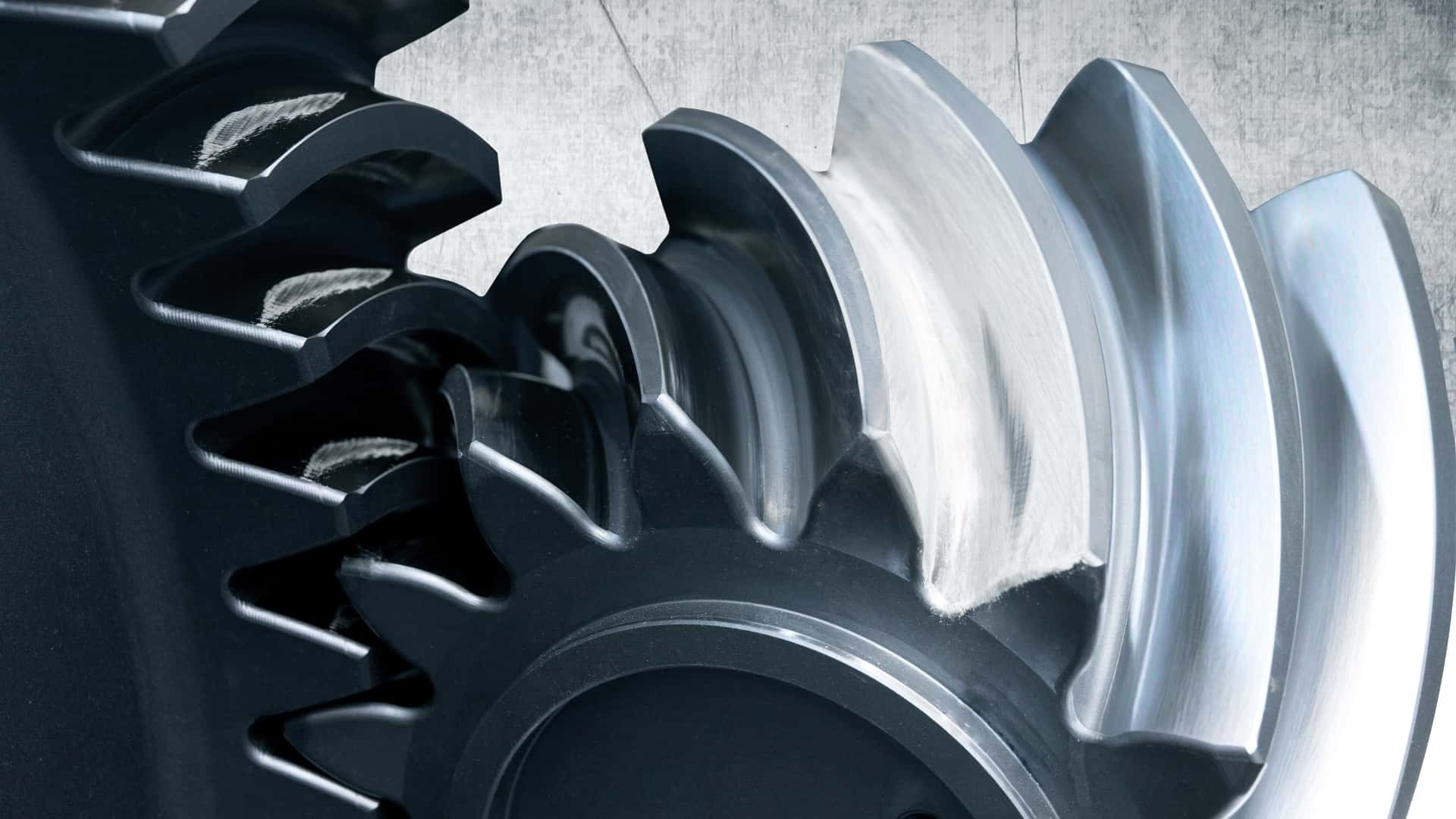
Edge Contact
Unintended contact near the tooth top, root, or side edge deserves attention because it can raise local loading. The cause may be tooth geometry, bearings, housing, alignment, or actual load, so edge contact should trigger a wider setup check rather than an immediate machining conclusion.
Common Contact Pattern Problems and What to Check
| Contact Pattern Issue | Possible Contributors | What to Check |
|---|---|---|
| Pattern too close to toe | Mounting distance or alignment variation | Pinion position, backlash, setup condition |
| Pattern too close to heel | Gear position, mounting, or load-position variation | Gear mounting, bearing support |
| Pattern near tooth edge | Misalignment, deflection, or assembly variation | Shaft, housing, assembly accuracy |
| Pattern too narrow | Limited contact, geometry, or light checking load | Backlash, tooth geometry, load condition |
| Pattern too wide or heavy | Tight mesh or checking-condition variation | Backlash, setup load, marking method, mounting position |
| Different drive/coast pattern | Direction, setup, or checking-method difference | Rotation direction and inspection method |
Use the table above for initial troubleshooting only; more than one factor may be involved.
Why Contact Pattern Should Be Reviewed With Backlash and Mounting Distance
Contact pattern, backlash, and mounting distance describe related parts of the same mesh and are best reviewed together.
Too little backlash can make the set run tight and alter the mark; an incorrect mounting distance can move the pattern toward the toe or heel. A single gear can therefore meet its dimensions while the assembled pair still needs adjustment.
For matched bevel sets, these checks should be agreed before sampling. If only one member is being replaced, review the old mating gear and assembly condition as part of the matched-pair assessment.
Do not diagnose from the mark alone. A shifted pattern can come from mounting or assembly conditions as well as tooth geometry.
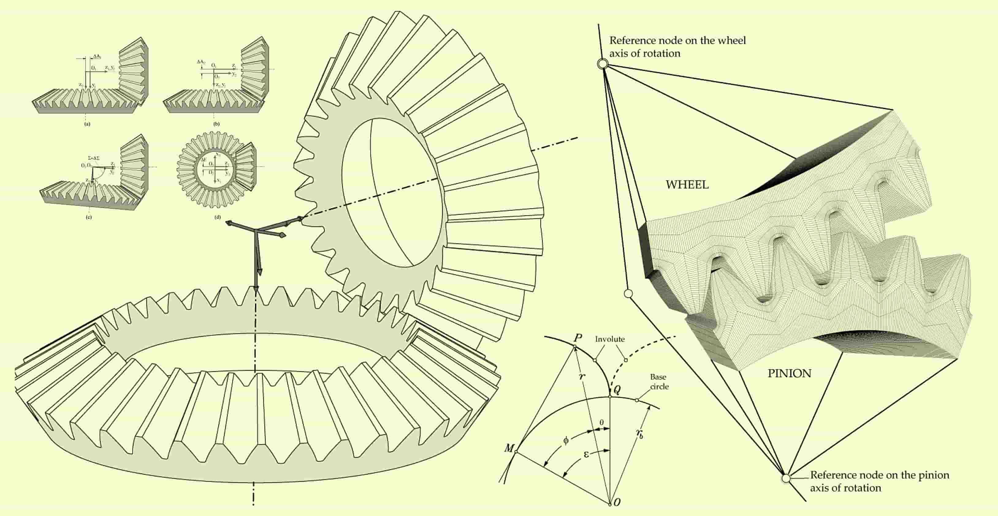
What Should Be Confirmed Before Approving a Bevel Gear Set?
| Check Item | Why It Matters |
|---|---|
| Drawing or gear data | Confirms gear geometry and design basis |
| Matched pair and mating gear | Shows whether both members belong together and whether wear may affect the result |
| Mounting distance | Affects contact position and backlash |
| Backlash requirement | Confirms the intended tooth clearance |
| Contact pattern and tooth side | Shows the contact location and whether drive or coast flank is being checked |
| Rotation direction | Confirms the load direction used for review |
| Inspection scope | Defines required photos, measurements, or reports |
| Assembly feedback | Connects the inspection result with real installation behavior |
If these inputs are incomplete, only a preliminary judgment may be possible. For high-accuracy, noise-sensitive, or high-load sets, define contact-pattern acceptance, mounting distance, backlash, and inspection scope during quotation rather than after sampling.
Common Mistakes When Reading Bevel Gear Contact Patterns
Judging a Photo Without Checking the Setup
A photo can be useful, but camera angle, marking compound, running condition, and test load can all change what it shows. Confirm the setup before treating the image as evidence of a gear error.
Ignoring Mounting Distance and Backlash
A shifted or heavy pattern does not automatically mean the teeth were cut incorrectly. Mounting distance and backlash can move the contact area, so both should be checked before rework or redesign.
Replacing Only One Gear Without Reviewing the Pair
For many spiral bevel, hypoid, and ring-and-pinion sets, replacing one member against a worn mate can change the expected pattern. Review the mating gear and installation condition first.
Treating Contact Pattern as the Only Inspection Result
Contact pattern is one part of the release decision. Gear accuracy, hardness, material, key dimensions, and assembly requirements may also need to be confirmed.
How PairGears Reviews Bevel Gear Contact Patterns
PairGears reviews bevel gear contact patterns with the drawing, mating-gear data, mounting distance, backlash, rotation direction, and inspection requirements. The aim is to judge the gear pair in its actual assembly context, not simply whether a mark appears on the tooth surface.
For replacement work, sample photos, wear marks, OEM numbers, and the condition of both members are considered together. A worn contact mark is treated as project evidence, not as a design target to copy. The review may still require gear geometry, material, heat treatment, accuracy grade, inspection scope, and, when necessary, sample measurement or prototype confirmation.
Need help reviewing a bevel gear contact pattern?
Send the available drawing, contact-pattern photos, mating-gear data, mounting distance, backlash requirements, rotation direction, and assembly feedback.
FAQ About Bevel Gear Contact Patterns
What does a bevel gear contact pattern show?
It shows where the tooth flanks touch under a defined checking condition and helps assess contact position and meshing behavior.
Can contact pattern alone prove a bevel gear set is correct?
No. Review it with mounting distance, backlash, mating-gear condition, rotation direction, and the inspection setup.
Why does the contact pattern move toward toe or heel?
A toe or heel shift can come from mounting distance, backlash, alignment, bearing support, or load condition. The cause cannot be confirmed from the mark alone.
Should bevel gears be replaced as a matched pair?
Not always. For spiral bevel, hypoid, and ring-and-pinion sets, however, contact and backlash depend on both members and their mounting position. Replacing one member requires the mate and setup to be reviewed.
What should buyers send for contact pattern review?
Send drawings, sample and contact-pattern photos, mounting distance, backlash requirements, mating-gear data, rotation direction, and assembly feedback.
Conclusion
A bevel gear contact pattern makes tooth contact visible, but the mark only has meaning in context. Mounting distance, backlash, drive/coast side, rotation direction, bearing support, mating-part condition, and the inspection setup all influence what you see.
Before approving or replacing a bevel gear set, review the pattern together with the complete gear-pair data.
Send Your Bevel Gear Set for Review
If you need help checking a drawing, sample, mating gear, or contact-pattern photo, contact us with the available project information for a technical review and quotation.