Gears in Motion: Understanding the Mechanics of Gear Operation
- Share
- publisher
- pairgears
- Issue Time
- Jul 3,2024
Summary
This blog explains how gears work, using gearbox examples, and includes technical parameters and formulas to showcase our expertise.
Introduction
Gears are mechanical components that play a crucial role in many types of machinery. They are used to transfer motion and power between machine parts, making them essential in applications ranging from simple devices to complex industrial machinery. In this blog, we will delve into the working principles of gears, particularly focusing on their use in gearboxes.
How Gears Work
Gears operate based on the principle of rotational motion and torque. A gear is a wheel with teeth that mesh with the teeth of another gear to transmit torque and rotational motion. The fundamental concept is that gears change the speed, torque, and direction of a power source.
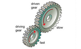
When two gears mesh, the motion of one gear causes the other to move. The gear that receives the initial motion is called the driver gear, while the gear that receives motion from the driver gear is called the driven gear. The interaction between the teeth of the gears ensures smooth transmission of motion.
Gearbox Example
A gearbox is an excellent example to understand gear operation. It consists of multiple gears arranged to achieve different gear ratios. These gear ratios determine the speed and torque output.
1. Gear Ratios:
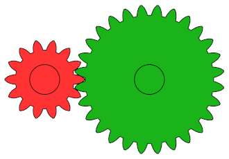
The gear ratio is the ratio of the number of teeth on two meshing gears. It determines the mechanical advantage and speed reduction. For example, if a driver gear with 20 teeth meshes with a driven gear with 40 teeth, the gear ratio is 1:2. This means the driven gear will rotate at half the speed of the driver gear but with twice the torque.

2. Torque and Speed:
The relationship between torque and speed in gears follows the principle of conservation of power. When gears of different sizes mesh, the torque is inversely proportional to the speed. This means a larger gear will produce more torque but rotate more slowly than a smaller gear.

Technical Parameters
1. Pitch Circle Diameter (PCD):
The diameter of the circle through which the gear teeth are evenly spaced.
2. Module:
A parameter that defines the size of the gear teeth, calculated by dividing the pitch diameter by the number of teeth.

3. Pressure Angle:
The angle between the line of action (the line along which the force is transmitted) and the normal to the gear teeth.
Applications
Gears are used in various applications, including automotive transmissions, industrial machinery, clocks, and wind turbines. Their ability to modify torque and speed makes them invaluable in mechanical systems.
Conclusion
Understanding the principles of how gears work is fundamental for anyone involved in mechanical engineering or machinery design. Gears are integral components that ensure efficient power transmission and motion control. At PairGears, we pride ourselves on manufacturing high-quality gears that meet the demands of various applications.The video on the right can take you further to understand the basics and applications of gear.To enhance understanding, consider the following resources:
Should you have any questions or require further assistance, please do not hesitate to contact our engineer: ben@pairgears.com.