Gear spline Types and Machining Methods: A Practical Guide
- Share
- publisher
- Jessica
- Issue Time
- Jan 5,2026
Summary
Gear spline types and gear spline machining methods explained. PairGears aligns fit, heat treat and inspection for agriculture, truck, construction and EV.

1. Introduction
Gear Spline are everywhere in power transmission, yet many spline projects fail for a simple reason: the part looks correct on a drawing, but the fit and assembly behavior are not fully defined. As a precision gear manufacturer and custom gear supplier, PairGears sees the same issues repeatedly—parts that won't slide in, parts that need force, or parts that assemble easily but develop play.
This article explains Gear splines in a practical, factory-friendly way: what a Gear spline is, why it matters, the common Gear spline types, and the most used Gear spline machining routes for internal and external Gear splines. We also share what information helps the first build succeed and how to choose a supplier who can keep Gear spline fit stable from prototypes to production.
2. What Is a Gear Spline
A Gear spline is a multi-tooth shaft–hub connection that transmits torque while helping locate and center the mating parts.

3. Why Gear Spline Matter in Real Assemblies
Is a Gear spline always "better" than a key connection? Not always—but in many drivetrain and industrial applications, gear splines are chosen because they solve three real problems at once.
First, gear splines share load across multiple teeth. That usually means higher torque capacity and better durability—if tooth form, material, and heat treatment are matched to the duty cycle.
Second, gear splines can be designed for controlled centering and predictable assembly. When the centering method (flank/major/minor) and the target fit are clearly defined, gear splines can deliver repeatable assembly feel and stable performance across batches.
Third, gear splines are ideal when you need torque transmission with axial movement. Sliding gear splines appear in systems where positioning, service, or motion requires axial travel while still carrying torque.
4. Common Gear Spline Types
Below are the Gear spline profiles you will encounter most often in transmission components.
Tooth Form | Typical Centering | Best Fit For | Practical Notes | |
Rectangular (Straight-Sided) | Straight flanks | Major/minor diameter centering | Medium loads, simple hubs, sliding connections | Simple geometry; requires a clear plan for distortion and tooth thickness control |
Involute Spline | Involute-like profile | Flank centering (common), or major/minor | Higher torque, better load sharing, tighter centering needs | Most common in demanding drivetrain work; strong tooth root and good fatigue behavior |
| Serration / Triangular | Fine teeth, small pitch | Often diameter-based | Light loads, small diameters, thin-wall hubs, tools | Useful where packaging is tight; typically not used for very high torque |
Tip from the shop floor: most "fit disputes" happen because the Gear spline type is chosen, but centering method and acceptance gaging are not.

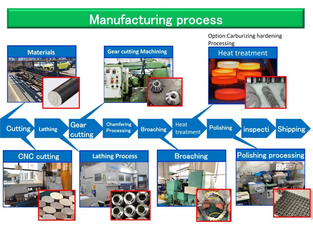
5. Gear Spline Machining Methods in Production
Spline machining choices depend on whether it’s an internal spline or external spline, required accuracy, material state (soft vs hardened), and production volume.
Internal gear spline machining
● Broaching: A high-efficiency method for internal splines, especially suitable for stable, repeatable high-volume production. It often provides excellent consistency when tooling and setup are well controlled.
● Shaping (gear spline shaping): More flexible than broaching and suitable for small batches, prototypes, or parts where broaching is not practical due to geometry or tooling constraints.


External gear spline machining
● Hobbing: Efficient and widely used for external splines and gear-like profiles. Great for volume production when accuracy and process stability are designed in.
● Milling: Flexible for prototypes, small batches, or special forms. It can be a cost-effective route when volumes don’t justify dedicated tooling.


Forming routes (for selected high-volume cases)
Cold rolling / forming: Forms teeth by plastic deformation rather than cutting. It can improve material utilization and surface integrity and is attractive for certain large-volume spline shafts. The trade-off is that forming demands tighter upstream blank control and a clear size path to reach the final tooth thickness and fit.
Finishing and correction (when accuracy requirements are higher)
After heat treatment, distortion can shift tooth thickness, runout, and fit. Depending on the product and requirement, finishing may involve controlled correction steps and tighter inspection routines. The key point is not the "name of the process" but whether the route keeps the spline fit stable after hardening.
6. Who Uses Gear Spline in PairGears' Four Focus Sectors
Gear spline are common across all four PairGears application sectors:
● Agricultural machinery: PTO-style connections, drive shafts, sliding couplings designed for service and field conditions
● Heavy truck: drivetrain shafts and couplings where stable fit and long-life torque transfer matter
● Construction equipment: high-torque interfaces under shock loading and harsh environments
● EV-related systems: e-drive interfaces, auxiliary mechanisms, and test rigs needing repeatable fit and reliable alignment
7. Key Features That Decide Spline Fit and Consistency
In practice, spline success comes down to a few "decision features" that must be aligned early.
| Feature | What It Means for Customers | What Can Go Wrong | What PairGears Aligns Early |
Centering method | How the assembly finds center | “Looks right” but runs off-center | Flank vs major/minor centering defined in RFQ |
Tooth thickness / backlash | Assembly feel and serviceability | Too tight, too loose, inconsistent | Target fit + acceptance method (gauge or measurement) |
| Lead/contact stability | Load sharing across face width | Edge contact, uneven wear | Process route + inspection items tied to function |
| Heat treatment effect | Distortion and hardness influence fit and life | Post-HT shift causes fit failures | Allowance plan + distortion window + correction strategy |
| Inspectability | Same "good part" definition on both sides | Supplier passes, customer rejects | Agreement on gauging/inspection before sampling |

8. Benefits at a Glance
| Benefit | What You Get | Why It Matters |
Higher torque capacity | Load shared by multiple teeth | Supports heavy-duty drivetrains and long-life targets |
Better centering potential | More predictable alignment | Improves assembly consistency and functional stability |
| Sliding torque transfer | Torque with axial movement | Useful for couplings and service-driven designs |
| Repeatable production fit | Lower rework and fewer “first build” surprises | Faster launches and more stable batch performance |
| Flexible design options | Many fit/centering strategies | Helps solve packaging and assembly constraints |
9. How to Choose a Gear Spline Supplier
Use these checks to reduce first-build risk and improve batch stability:
1.Confirm centering method and fit in writing (flank vs major/minor, tight vs sliding) before samples are made.
2.Ask how heat treatment distortion is managed (allowance plan, correction approach, and how tooth thickness is protected).
3.Align acceptance and inspection methods (Go/No-Go gauge, span/pins, CMM/measurement plan) so both sides judge parts the same way.
4.Match the process route to your volume (prototype vs mass production routes should not be forced into one method).
5.Look for stability controls (process records, traceability, and monitoring of critical fit-related dimensions).
10. Why Choose PairGears
PairGears is a precision gear manufacturer and custom gear supplier focused on practical transmission components—not just nominal dimensions.
● Fit-first engineering: we prioritize assembly behavior and stability, not only drawing compliance.
● Process-matched spline machining: routes selected by spline type, volume, material, and accuracy target.
● Heat-treatment-aware planning: allowance and distortion control are built into the route from the beginning.
● Aligned inspection: we help define acceptance methods early to reduce first-build disputes.
● Four-sector application experience: agriculture, heavy trucks, construction equipment, and EV-related systems.
11. FAQ
Q1: What's the difference between rectangular and involute Gear Spline?
A: Rectangular splines use straight flanks and are often used for medium-load designs. Involute splines typically offer better load sharing and fatigue strength, making them common for higher torque transmission work.
Q2: What is flank centering and why is it common?
A: Flank centering uses the tooth sides to locate the mating parts. It is common because it can support more even load sharing when fit and inspection are aligned.
Q3: Which Gear Spline machining method is best for internal spline—broaching or shaping?
A: Broaching is often best for volume and repeatability when tooling is justified. Shaping is more flexible for prototypes, smaller batches, or certain geometries.
Q4: Why do Gear Spline parts often fail at first assembly?
A: Usually because centering method, tooth thickness/backlash targets, heat treatment impact, and acceptance gaging were not fully aligned early.
Q5: What does PairGears need to evaluate a spline project quickly?
A: Drawings or samples, mating part details, torque/speed and duty cycle basics, heat treatment requirements, and the acceptance method you plan to use.
12. Conclusion
Gear splines are not "mysterious parts" but they are easy to get wrong when key details are left as assumptions. The fastest way to improve first-build success is to define the spline type, centering method, target fit, heat treatment route, and inspection/acceptance method as one connected package.
If you are developing a new gear spline, replacing a worn component, or troubleshooting a fit that is too tight, too loose, or inconsistent. Contact Us to Share your drawing (or sample), mating part information, and duty basics—PairGears will recommend a controllable gear spline machining and inspection plan that supports stable assembly and long-term reliability.