Gear Shaft Guide Types Features and Buying Tips
- Share
- publisher
- Jessica
- Issue Time
- Jan 20,2026
Summary
Gear shaft basics: definition, operation, common types, key design features, and supplier tips for stable torque transfer and repeatable assembly.

1. Introduction
Gears often get the spotlight, but the shaft that carries them can decide whether an assembly feels smooth and stays stable over time. A gear shaft holds the key reference surfaces (bearing seats, faces, fits) that keep gears aligned while they transmit torque.
The terms can be confusing. In vehicles, a "drive/propeller shaft" often means the long shaft to the axle. A gear shaft usually means an internal shaft that carries gears (fixed, keyed, or splined) between stages. PairGears supports Agricultural Machinery, Truck, Construction Equipment, and EV drivetrain—this guide explains what a gear shaft is, how it works, common types, and what to check when choosing a supplier.
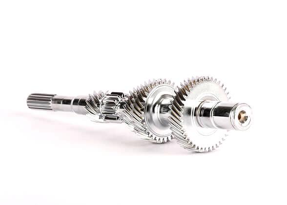
2. What is a gear shaft?
A gear shaft is a rotating shaft designed to carry gears (or gear features) and transmit torque and speed while maintaining alignment at the bearing and mounting datums.

3. Why gear shafts matter more than most people expect
A gear shaft works by supporting gears on accurate seats and faces while the mounted gears mesh with mating gears to transfer torque. If the shaft does not control runout, concentricity, and face squareness at the gear and bearing locations, load distribution can shift and assembly feel can vary—even when parts pass basic size checks.
Early risk points are often not the "big numbers" on the drawing, but the relationships: gear location to bearing seats, fit to mating hubs, and the stability of the shaft's datum chain after heat treatment or finishing. When these relationships drift, results vary unit-to-unit: one assembly feels smooth while another feels rough or runs hotter.
Cost and lead time are route decisions too. A flexible route can be ideal for prototypes and small batches, while stable volume production needs controlled fixtures, tool management, and repeatable inspection. The goal is simple: control the main risk point (fit, alignment, durability, or delivery) and keep batch-to-batch output stable.
4. Common types of gear shafts
| Category | Type | What it means | Typical use case |
role in a drive | Shafts positioned to route torque through stages | Multi-stage transmissions and industrial reducers | |
torque connection | Keyed shaft | Torque transmitted through a key + keyway | General industrial drives, moderate torque |
torque connection | Splined shaft | Torque transmitted through multiple spline teeth | Higher torque density, repeatable positioning, serviceable assemblies |
torque connection | Interference-fit shaft | Torque via press fit between shaft and gear/hub | Compact assemblies where slip must be prevented |
structure | Solid shaft | High stiffness for a given diameter | Heavy-duty and shock-load conditions |
| structure | Hollow shaft | Lower mass and inertia with good stiffness design | Weight-sensitive systems and faster response |
| integration | Assembled gear-on-shaft | Gears mounted onto a shaft (key/spline/fit) | Serviceability, flexible configurations |
| integration | Integrated gear shaft | Gear features machined as part of the shaft | Fewer interfaces, strong datum control in production |
Selection note: The best choice depends on torque, space, service needs, and how tightly you must control alignment across batches. If your project uses the term "transmission shaft" clarify whether it means an internal gear-carrying shaft or an external driveline shaft—this avoids mismatched tolerances and inspection expectations.


5. Who uses gear shafts in PairGears' four sectors
5.1 Agricultural Machinery
Gear shafts are widely used in agricultural machinery drivetrains, where long working hours and changing loads are common. They transmit power between stages and keep gears aligned so torque can be delivered reliably in the field. In these machines, stable fits and durable shaft surfaces help maintain consistent operation over time.
5.2 Truck
In truck transmissions and axle-related systems, gear shafts carry gears that transfer high torque across multiple stages. They help control speed and torque changes while keeping alignment stable under continuous service. For these applications, consistent geometry and reliable interfaces (such as splines or press fits) support repeatable assembly and long service life.
5.3 Construction Equipment
Gear shafts are essential in construction equipment where shock loads, frequent starts/stops, and harsh environments are typical. They transmit power through reduction stages and support stable gear engagement during demanding duty cycles. In these systems, toughness, wear resistance, and secure torque connections are key to reliable operation.
5.4 EV Drivetrain
In EV drivetrain, gear shafts support compact, efficient power transfer at higher speeds. They carry gears between stages and help maintain alignment so the system runs smoothly and efficiently. Here, stable runout control, fit consistency, and good surface quality help reduce variation across batches.
6. Key design and manufacturing features to watch
| Feature area | What to specify / verify | Why it matters |
Datum chain and alignment | Bearing seats, gear locating faces, shoulders, center distances | Stable alignment supports consistent gear contact under load |
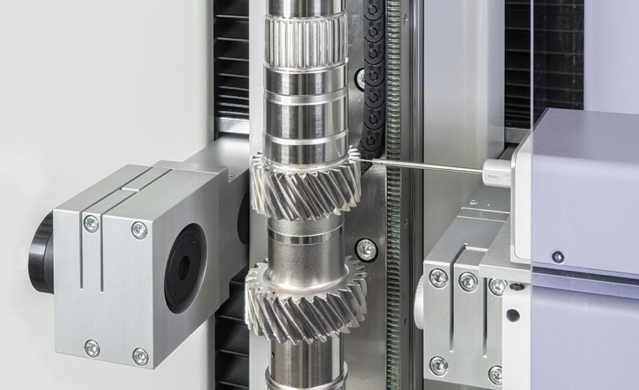
Runout and concentricity | Runout at bearing seats and gear mounting areas | Reduces assembly variation and improves load distribution |
| Torque interface | Keyway quality, spline accuracy, press-fit design | Helps prevent slip, fretting, and premature wear |
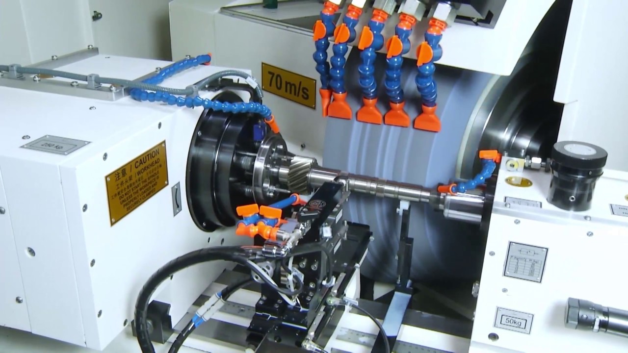
| Material and heat treatment | Alloy choice, case hardening vs through hardening (as required) | Controls fatigue strength, wear resistance, and durability |
| Surface quality | Seat roughness, contact faces, fillet transitions | Supports fit stability and reduces wear |
Fillets and stress control | Shoulder fillets, undercuts, transition radii | Reduces stress concentration and fatigue risk |
Traceability and marking | Batch/lot marking, interface protection | Helps prevent mix-ups and supports repeat-order control |
Practical check: For many programs, the most useful early evidence is not a long report, but a clear set of datum-related measurements—runout at seats, face squareness, and the fit features (keyway/spline/press-fit) that carry torque. Align these checks with your assembly method so incoming inspection focuses on what actually drives consistency.
7. Benefits of well-made gear shafts
| Benefit | What you get | Practical outcome |
Efficient torque transfer | Low losses at interfaces and stable rotation | Better system efficiency and predictable output |
Compact integration | Gear stages packaged on optimized shafts | Reduced space and simpler layouts |
| Controlled speed/torque behavior | Works with gear ratios to shape performance | Easier system tuning and stable behavior |
| Durability under load | Strong materials and correct interfaces | Longer service intervals and fewer failures |
| Repeatable assembly | Stable datums and fits across batches | Less rework and fewer one-off issues in production |
8. Supplier selection checklist
● Alignment capability: Ask how the supplier defines and controls the datum chain (bearing seats, faces, gear locations). Confirm they can provide the inspection evidence that matches your drawing and assembly method.
● Interface experience: Verify proven process control for keyways, splines, and press fits—especially for higher torque programs. Small interface errors often become large assembly variation.
● Heat-treat risk control (if applicable): If heat treatment is required, check how distortion is managed and how fit stability is verified after processing. A good route plans correction and finishing only where it adds functional value.
● Repeatability system: Look for fixture discipline, tool-life management, lot traceability, and change control. These systems protect batch-to-batch consistency when volume scales.
● DFM communication: Choose a supplier who can identify the main risk points quickly and propose a practical route with clear assumptions. Speed matters, but clarity matters more than vague promises.
9. Why Choose PairGears
● Transmission-focused understanding: We consider shafts and gears as one assembly system—datums, fits, and torque interfaces—so recommendations remain practical for manufacturing and assembly.
● Four-sector application experience: Agricultural machinery, Truck, construction equipment, and EV drivetrain each prioritize different risk points. We adjust route and controls to fit the duty cycle.
● Practical route planning: We aim for a manufacturable path that controls the main risk point and reduces scrap and rework. Where needed, we propose finishing only where it improves functional results.
● Quality-aligned deliverables: Based on your drawing and requirements, we can align inspection planning and traceability expectations (for example, material certification and key datum checks when specified).
● Responsive quoting: Share a drawing, sample, or OEM number plus key requirements and volume plan. We return feasibility notes and a quote range efficiently.

10. FAQ
Q1: Is A Gear Shaft The Same As A Drive Shaft?
Not exactly. A drive/propeller shaft often transfers power to an axle, while a gear shaft typically carries gears and defines internal alignment and fits within a drive stage.
Q2: When Should I Choose Splines Instead Of A Keyway?
Splines are often preferred for higher torque density, more repeatable positioning, and serviceable assemblies. The best choice depends on torque, packaging, and maintenance requirements.
Q3: What Information Most Affects Gear Shaft Cost?
Material and heat treatment, tolerance on bearing/gear seats, spline or keyway complexity, and inspection requirements usually drive cost more than overall length alone.
Q4: Do Hollow Shafts Always Save Cost?
They can reduce weight and inertia, but manufacturing and inspection may be more complex. Choose hollow shafts when system-level benefits justify the added process control.
Q5: What Do You Need To Start A Quotation?
A drawing is best (including material and heat treatment). If you don’t have one, send a sample photo set or an OEM number plus torque/speed, duty cycle, and expected volume.
11. Conclusion
A gear shaft is the backbone that keeps gears aligned while torque and speed move through a machine. Reliable programs treat shaft design as a datum-and-interface problem: control alignment, choose the right torque connection (key/spline/fit), and plan materials and processing so results stay consistent from first article to repeat orders.
If you have a drawing, sample, or OEM number, Contact us. We can review feasibility, suggest a practical manufacturing route, and support stable assemblies with batch-to-batch consistency based on your application and volume plan.