Gear Manufacturing Process: A Step-by-Step Overview
- Share
- publisher
- Jessica
- Issue Time
- Jan 5,2026
Summary
A neutral, end-to-end overview of gear manufacturing—from blanks and tooth cutting to heat treatment, finishing, inspection, and documentation.

1. Introduction
Gear manufacturing is not a single operation. It is a controlled process chain—material selection, blank preparation, tooth generation, heat treatment, finishing, and inspection—designed to produce gears that meet defined requirements for strength, accuracy, noise, and service life.
This article provides a neutral, end-to-end overview of how gears are typically made in industrial production. It focuses on what each stage controls, what commonly goes wrong, and how quality is verified with measurable inspection outputs.
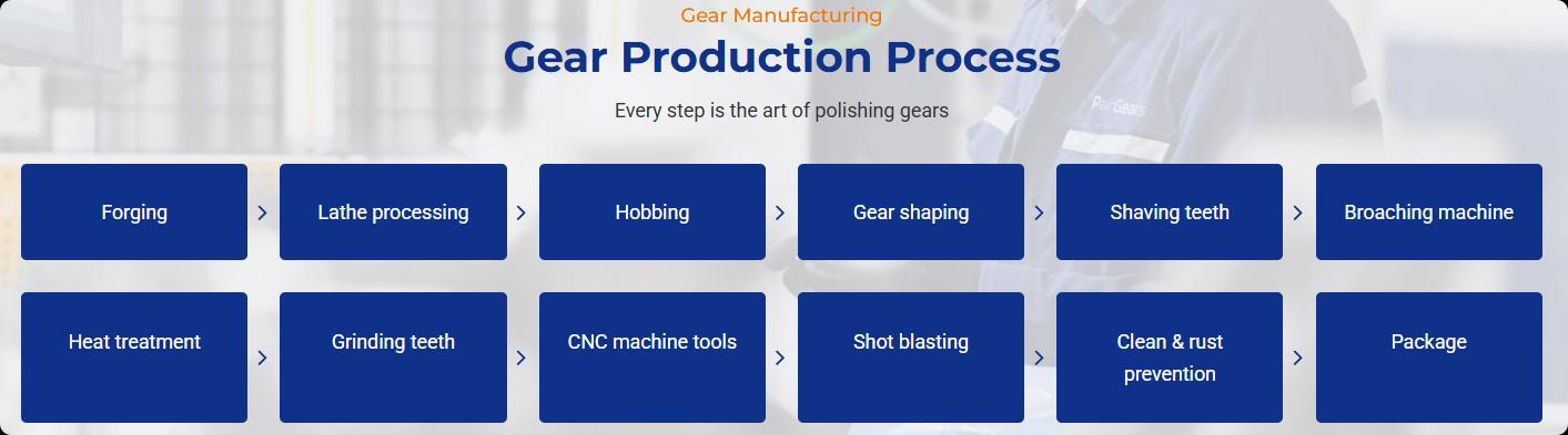
A typical gear production flow can be described as:
1. Forging – Form the gear blank with controlled material flow and core integrity.
2. Lathe Processing – Turn key datums (bore/OD/faces) to establish concentric references for tooth cutting.
3. Hobbing – Generate external gear teeth efficiently for many spur/helical gear designs.
4. Gear Shaping – Cut teeth where geometry or access makes shaping more suitable (commonly for internal forms or constrained features).
5. Shaving Teeth – Improve tooth surface and geometry (often used as a pre-heat-treatment finishing step in volume production).
6. Broaching Machine – Produce internal profiles (e.g., internal teeth/splines) with high repeatability in suitable volumes.
7. Heat Treatment – Achieve required hardness and fatigue/wear performance (while managing distortion risk).
8. Grinding Teeth – Bring tooth geometry into final tolerance and improve surface quality after hardening.
9. CNC Machine Tools – Finish associated features (keyways, threads, grooves, mounting faces) to final spec.
10. Shot Blasting – Clean surfaces and remove scale/oxide for consistent appearance and subsequent protection.
11. Clean & Rust Prevention – Final cleaning plus anti-corrosion protection (oil/VCI) to preserve surfaces in storage/shipping.
12. Package – Protective packing to prevent corrosion, impact damage, and tooth-to-tooth contact.
2. What is Gear Manufacturing
Gear manufacturing is the set of processes used to produce a gear’s functional tooth geometry and reference datums to a specified accuracy, strength, and surface condition so it can transmit torque reliably.
3. Why Gear Manufacturing Process Control Matters
3.1 Accuracy is created across multiple steps, not “fixed at the end.”
Tooth geometry depends on stable datums and consistent stock allowance. If the blank or datums vary, downstream finishing cannot always recover the intended contact pattern and noise behavior.
3.2 Heat treatment changes both performance and geometry.
Case hardening processes are widely used because they create a hard, wear-resistant surface over a tougher core, improving fatigue and wear behavior. But hardening can also introduce distortion that must be anticipated with allowances and finishing plans.
3.3 Inspection is what makes manufacturing repeatable.
Modern gear acceptance typically relies on measurable parameters such as tooth profile, helix/lead, pitch deviations, and runout (with standards such as ISO systems of accuracy). ISO 1328, for example, establishes a tolerance classification system for cylindrical involute gears relevant to manufacturing and conformity assessment.
4. Major Gear Manufacturing Routes and Methods
4.1 Manufacturing routes (by how the gear body is formed)
| Route | Typical starting form | Strengths | Common trade-offs |
Cut-from-solid machining | bar/forged preform + turning | Flexible design changes; good for many sizes | More machining time; depends on tooling/setup stability |
Forged blank + machining | hot/cold forging near-net | Better material flow for high-load gears | Tooling cost; tighter process window |
| Cast blank + machining | sand/investment casting | Large gears, complex shapes | Material/porosity control; more variability |
Powder metallurgy (PM) | compacted + sintered | Cost-efficient at high volume, small gears | Load capability and density limitations |
Hybrid / advanced multi-axis | integrated turning + skiving, etc. | Productivity + fewer setups | Higher equipment/tooling requirements |
4.2 Tooth generation methods (how the teeth are produced)
Common tooth cutting methods include hobbing, shaping, milling, broaching, and power skiving. Many factories select the method based on gear type (internal/external), shoulder access, batch size, target accuracy, and tool life economics.
• Hobbing: Widely used for external spur/helical gears in production.
• Shaping / Broaching: Often used for internal teeth and certain geometries where access is constrained.
• Power skiving: Increasingly used as a productive alternative for internal gears/splines under suitable rigidity and setup conditions; both Sandvik and Gleason describe it as a viable alternative to shaping in many cases.


4.3 Heat treatment types (how surface and core properties are achieved)
• Carburizing (case hardening): Carbon diffusion at elevated temperature to create a hard case; generally improves wear and fatigue resistance.
• Nitriding: Nitrogen diffusion to form a hard surface layer at relatively lower temperatures; often chosen when dimensional stability/low distortion is critical.
• Induction hardening: Localized hardening of selected areas; commonly used when only certain zones require high hardness.


4.4 Finishing types (how geometry and surface are refined)
Finishing can include gear grinding, honing, lapping, and other surface refinement operations. Gear Technology notes that finishing operations such as grinding and honing are commonly used to improve the gear surface and noise behavior, sometimes in combination.


5. Users (Who This Guide Helps)
• Gear and drivetrain design engineers defining accuracy grade, material, and heat-treatment requirements
• Purchasing and sourcing teams comparing suppliers beyond price
• Quality engineers aligning inspection methods and acceptance criteria
• Maintenance and rebuilding teams diagnosing noise, wear, and contact issues
• Program managers balancing tooling, lead time, and batch stability
6. Features (Step-by-Step Process Chain and What Each Stage Controls)
6.1 Inputs: specification and design intent
A manufacturable gear starts with a clear definition of:
• gear type (spur/helical/bevel/worm/internal gear), module/DP, pressure angle, helix angle
• material and cleanliness requirements
• target accuracy system (e.g., ISO accuracy grades) and inspection plan
• heat-treatment targets (surface hardness, case depth, core hardness window)
6.2 Blank making (forging / casting / bar preparation)
Purpose: create a stable foundation with consistent geometry and stock allowance.
Key controls:
• concentricity and runout relative to intended datums
• sufficient machining allowance for post-heat-treat finishing (if required)
Common issues:
• uneven allowance → distortion becomes unrecoverable later
• poor datum strategy → tooth geometry scatter in batch production
6.3 Datum machining (turning, drilling, key reference features)
Purpose: establish reference surfaces before tooth generation.
Key controls:
• face runout, bore/shaft concentricity, datum integrity
Common issues:
• “good teeth, bad assembly”: teeth are correct but gear runs eccentric because datums drift
6.4 Tooth cutting (hobbing / shaping / milling / broaching / skiving)
Purpose: generate tooth geometry with planned stock for later steps.
Key controls:
• tool condition, machine rigidity, setup repeatability
• controlled stock allowance for finishing
Notes on method selection:
• hobbing is common for external gears; shaping/broaching are common for internal forms; skiving can improve productivity for internal gears and splines when conditions are suitable.
6.5 Deburring, edge conditioning, and cleaning
Purpose: remove burrs and sharp edges that can chip during handling or become crack initiators.
Key controls:
• consistent chamfers; controlled edge radii
• cleanliness before heat treatment (reduce contamination risk)
6.6 Heat treatment (carburizing / nitriding / induction)
Purpose: achieve required surface durability and fatigue resistance.
Key controls:
• target hardness and case depth; process stability and distortion control
• fixturing strategy; allowance planning for post-HT finishing
Industry note:
case hardening aims to produce a hard, wear-resistant surface over a tougher core; this is widely referenced in gear heat treatment discussions.
6.7 Finishing (grinding / honing / lapping / superfinishing)
Purpose: bring geometry into final tolerance and improve surface condition for noise and efficiency.
Key controls:
• tooth profile and lead correction
• surface texture control to support lubrication film stability
Industry note:
• finishing operations such as grinding and honing are frequently used to improve noise-related surface topography and final quality; honing can support smoother operation and reduced noise.
6.8 Inspection and documentation (metrology and acceptance)
A typical gear inspection plan focuses on:
• profile deviations, helix/lead deviations, pitch deviations, runout/composite errors
These concepts appear in standards and inspection practices (ISO accuracy systems and AGMA inspection guidance).
Practical outputs often include:
• analytical charts for profile/lead/pitch
• hardness and case depth verification (for case-hardened gears)
• traceability records linking material heat, furnace lot, and inspection results

6.9 Protection and packaging
Purpose: prevent corrosion and preserve accuracy during storage and transport.
Key controls:
• cleaning, anti-corrosion oil or VCI packaging, damage-resistant stacking
7. Benefits (What a Well-Controlled Process Delivers)
In practice, spline success comes down to a few "decision features" that must be aligned early.
Benefit | What it looks like in the field | What enables it |
Lower noise / smoother meshing | stable contact, less whine | finishing strategy + consistent geometry |
Longer wear life | less pitting/scuffing | correct heat treat + surface condition |
Batch consistency | fewer “good sample / bad batch” cases | stable datums + controlled allowance + metrology |
Clear acceptance | fewer disputes | standard-based inspection outputs |
8. Supplier Selection Suggestions (Neutral Checklist)
When choosing a gear supplier, a practical evaluation includes:
8.1 Ask for the process route, not just the quote
Supplier should state blank route → tooth cutting → heat treat → finishing → inspection outputs.
8.2 Confirm the accuracy system and inspection method
If ISO accuracy grades are used, confirm which standard basis is used and what will be measured (profile/lead/pitch/runout).
8.3 Distortion planning
Ask how stock allowance and fixturing are designed to control heat-treatment distortion.
8.4 Evidence over promises
Request sample inspection charts and hardness/case depth verification approach.
8.5 Internal features capability
If internal gears or splines are involved, confirm the planned method (shaping/broaching/skiving) and gauging strategy. Power skiving is often presented as a high-productivity option when conditions are suitable.
9. Further Reading
Internal deep-dives (PairGears blog)
• Gear cutting overview: What Is Gear Cutting? Processes and Applications
• Heat treatment overview: Gear Heat Treatment Guide: Carburizing, Nitriding, Induction
• Finishing overview: Understanding Gear Finishing: Gear Lapping, Honing, Grinding
• Gear spline manufacturing: Gear Spline Types and Machining Methods: A Practical Guide
External references
• ISO accuracy system overview: ISO 1328 (ISO Online Browsing Platform)
• AGMA inspection practice preview: AGMA 915-1-A02 (ANSI preview PDF)
• Industry process hub: Gear Technology – Processes
• Power skiving overview (machine-tool authority): Gleason – The Power Skiving Approach
• Tooling knowledge base: Sandvik Coromant – Gear manufacturing
10. FAQ
Q1. What is the typical sequence of a gear manufacturing process?
A: A typical sequence is: define specifications → make a stable blank → machine datums → generate teeth (cutting) → deburr/clean → heat treat → finish → inspect → protect and pack. The exact route varies with gear type (external vs internal), target accuracy, and whether post-heat-treat finishing is required.
Q2: Which tooth cutting method should be used: hobbing, shaping, milling, broaching, or skiving?
A: There is no universal “best” method. Hobbing is common for external gears; shaping and broaching are frequently used for internal forms. Power skiving is often discussed as a productive alternative for internal gears and splines when machine rigidity, tooling, and setup conditions are appropriate.
Q3: Why do many gears need finishing after heat treatment?
A: Heat treatment improves durability but can introduce distortion. Finishing operations (e.g., grinding, honing) refine tooth geometry and surface condition to meet final tolerance and noise requirements. Industry references commonly describe finishing as a way to improve surface topography and operational smoothness.
Q4: What inspection data should a buyer request?
A: At minimum, request measurable outputs covering tooth geometry (profile, lead/helix, pitch, runout/composite) and, for case-hardened gears, hardness and case depth verification. Standards and inspection practices (ISO/AGMA) provide structured terminology for these deviation categories.
Q5: How can risk be reduced when sourcing gears internationally?
A: Lock the accuracy system, inspection method, and heat treatment targets early; ask for the full process route; validate with samples and documented measurement outputs; and scale volume only after repeatability is demonstrated.
11. Conclusion
Gear manufacturing becomes reliable when each step has a defined purpose, measurable outputs, and a planned handoff to the next step—especially around heat treatment and the finishing/inspection strategy that follows. For readers who need deeper detail, the “Further Reading” section lists both standards-oriented references and step-specific process explanations.