Gear Cutting Guide: Types, Methods, and Supplier Tips
- Share
- publisher
- Jessica
- Issue Time
- Jan 19,2026
Summary
Factory guide to gear cutting: gear types, process options, and supplier tips to balance cost, precision, noise, and lead time at PairGears.

1. Introduction
In power transmission, "Can you make this gear?" is only the starting point. Buyers and engineers also care about smooth operation, reliable load capacity, lead time, and batch-to-batch consistency.
Gear cutting can produce repeatable tooth geometry at scale, but results depend on choosing the right gear type and process route for your tolerance, volume plan, and budget. In this guide, PairGears explains common gear types made by gear cutting, how key methods compare, and what to check when choosing a supplier.
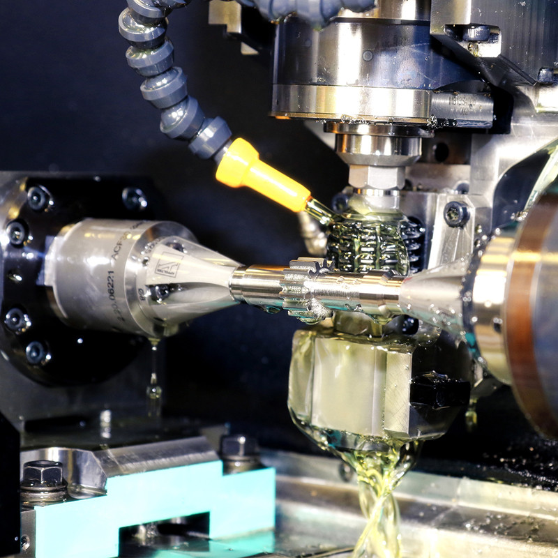
2. Gear cutting definition
Gear cutting is the machining of controlled gear tooth geometry on a gear blank using dedicated gear-forming processes.

3. Why gear cutting choice affects performance
Performance is driven by how teeth contact under load, not only by "passing" a few dimensions on the drawing. If a route does not control runout, datum repeatability, and tooth geometry stability, you may see vibration, uneven contact, or inconsistent backlash - even when parts appear acceptable in a basic check. These issues often surface later during assembly tests or field operation, where small geometric drift becomes a measurable system problem.
Key factors often overlooked early include tooth profile and lead, pitch variation, and the relationship between teeth and mounting datums (bore, shaft seat, faces). When these relationships drift, assembly variation shows up as unit-to-unit scatter: one unit runs fine while another feels rough, runs hotter, or shows a different contact pattern. That is why experienced teams link gear cutting, heat treatment, finishing, and inspection into one controlled route instead of treating them as separate steps.
Cost and lead time are process decisions too. Flexible routes work well for prototypes and small batches, while high-throughput routes rely on dedicated tooling and stable setups. The goal is to balance cost, quality, and delivery with repeatable risk control - so your production stays stable as volume scales.
4. Gear types commonly produced by gear cutting
| Gear type | What it does | Typical strengths | Common examples |
| Worm gear set (worm + wheel) | Large speed reduction in compact space | High ratio, compact layout | Small reducers, conveyors, steering and rudder systems |
| Bevel gear (straight/spiral/zerol/hypoid/mitre) | Transfers torque between intersecting or offset axes | Changes direction, strong torque capacity | Vehicle differentials, angle drives, power transmission |
| Spur gear | Parallel-axis power transfer with straight teeth | Simple, efficient, no axial thrust | General gear stages, machine tools, industrial transmissions |
Helical gear | Parallel-axis transfer with angled teeth | Smoother meshing, lower noise, higher load | High-speed transmissions, continuous-duty drives |
Herringbone (double helical) | High load with reduced axial thrust | Smooth running with lower thrust forces | Turbines, marine drives, heavy industrial gear trains |
Spur/helical gears fit parallel shafts, bevel/hypoid sets fit direction changes, worm sets fit compact high reduction (verify friction/heat), and herringbone gears reduce thrust but add cost and size.


5. Where these gears are used
5.1 Agricultural machinery
Long operating hours with mixed loads, plus dust and moisture exposure. Spur and helical stages are common; bevel gears often appear in angle drives and PTO modules. Consistent runout and stable backlash help reduce premature bearing and seal issues.
5.2 Heavy-duty truck
High torque density and long-life targets. Bevel/hypoid gears are common in axles and differentials; helical gears are common in transmissions. Batch consistency matters because variation can impact assembly time, warranty risk, and field reliability.
Shock loads, frequent start/stop, and harsh sites. Stable contact under load is critical; robust gear choices and controlled datums reduce pitting risk and unexpected noise under impact loads. Packaging and marking also matter because parts are often shipped in mixed sets.
5.4 EV drivetrain
Higher speeds and stricter noise targets. Helical gears are common, and finishing plus tighter inspection may be needed to keep results consistent from unit to unit. Clear process control helps avoid scatter that is noticeable in end-user experience.
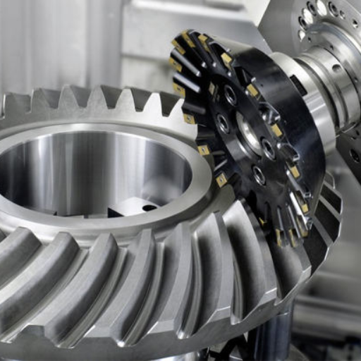
6. Gear cutting methods and key features
| Method | Best fit | Key features you get | Practical notes |
Gear hobbing | Most external spur and helical gears | Fast, scalable tooth generation | Often the best cost/performance baseline for repeat orders |
Gear shaping | Internal gears and some external gears | Flexible geometry, good for internal teeth | Cycle time can be higher than hobbing for volume |
| Gear milling | Prototypes, low volume, special forms | Low tooling cost, fast changeover | Requires strong setup discipline to keep consistency |
| Broaching (where applicable) | Very high-volume internal forms | Extremely short cycle time | High tooling cost; economical only at large volume |
| Gear grinding (finishing) | High precision or low noise needs | Best accuracy and surface finish | Used selectively for tight tolerance projects |
Gear cutting is usually a route: cut teeth, heat treat if needed, then finish only where it improves function—choose the route that controls your main risk (tolerance, load, lead time) while reducing scrap and rework.
Open learning reference: For an overview of hobbing/shaping concepts, see the NPTEL (IIT) Spur and Helical Gear Cutting course


7. Benefits of gear cutting for production
| Benefit | What it means in production | When it matters most |
Speed | High output once setup is stable | Repeat orders and volume ramps |
Precision control | Tooth geometry can be measured and improved | Tight assembly fits and consistent running |
| Cost efficiency | Competitive cost per part for many gear types | When balancing scrap, rework, and throughput |
| Broad applicability | Supports many gear families and sizes | Multi-model programs and mixed product lines |
| Process repeatability | Stable results with controlled tooling and datums | Predictable batch-to-batch performance |
Scalable quality plan | Inspection effort can scale with risk | When switching from prototype to mass production |
In short, gear cutting offers a strong balance of speed and controllability, with an upgrade path to higher precision when your application truly needs it.
8. Supplier selection checklist
● Capability match: confirm the supplier can run the route you need (hobbing, shaping, finishing) and can support your gear type. For matched sets, ask how pairing and marking are managed from production to shipping.
● Quality depth: ask how they control blank datums, runout, and distortion risk (if heat treated). Request a sample inspection list: size checks, runout, hardness, and gear geometry checks when specified by your drawing or quality plan.
● Repeatability evidence: look beyond one-off samples. Tool life management, change control, traceability, and process records are what keep batches stable over time, especially after engineering changes or supplier ramp-up.
● DFM speed and clarity: a strong supplier flags risk points early (datums, tolerances, heat treatment, finishing needs) and proposes a cost-effective route with clear assumptions rather than vague promises.
● Packaging and delivery control: confirm tooth-surface protection, corrosion prevention, and labeling standards. These details reduce receiving errors, handling damage, and mixing risks in your warehouse and assembly line.
9. Why Choose PairGears
PairGears focuses on custom precision gears that must assemble smoothly and run reliably in demanding sectors. Our approach is simple: select the right gear type, control the process route, and verify what matters with practical inspection and clear communication.
● Sector experience across agricultural machinery, heavy-duty truck, construction equipment, and EV drivetrain - with attention to real duty cycles, not only drawings.
● Process planning based on tolerance, volume, and noise targets - choosing the route that best balances cost, throughput, and repeatability.
● Quality mindset: datum control, runout management, and distortion risk control when heat treatment is required, plus inspection aligned to your key functional points.
● Buyer-friendly deliverables: traceable part marking, matched-set pairing support when needed, and inspection records as required (e.g., dimensions, runout, hardness, and gear geometry when specified).
● Fast response: share your drawing/sample/OEM number and key requirements to receive a feasible route and a quote range for your volume plan.

10. FAQ
Q1: Do I Always Need Gear Grinding For High Precision?
Not always. Grinding is most valuable when your application is sensitive to tooth geometry and surface condition, or when you need a tighter consistency window across batches. Many parts perform well with a stable cutting route, controlled heat treatment, and an inspection plan that targets the true risk points.
Q2: Spur Vs Helical - What Is A Simple Rule Of Thumb?
Spur gears are simple and efficient with minimal axial thrust, which helps keep the support design straightforward. Helical gears usually run smoother and quieter but create axial load, so bearing and housing design must support it. The best choice depends on speed, load, and your noise target.
Q3: When Should I Consider Bevel Or Hypoid Gears?
When you need to change power direction (often around 90 degrees) or you are building axle and differential systems where bevel/hypoid geometry is commonly used. For these projects, pairing, marking, and contact behavior are just as important as basic dimensions.
Q4: Is Broaching A Good Idea For Custom Gears ?
Usually no. Broaching shines in very high-volume programs where dedicated tooling is justified and geometry is stable. For custom or low-volume parts, flexible routes such as hobbing, shaping, or milling are often better for cost and lead time.
Q5: What Information Helps You Quote Fastest?
A drawing or OEM number, material and heat treatment requirements, target tolerance/inspection needs, expected volume, and a short note on the application priorities (load, noise, delivery). If you can share the mating gear details for a set, it also helps confirm fit and contact expectations.
11. Conclusion
Gear cutting can produce worm, bevel, spur, helical, and herringbone gears, but the best choice is the one that meets your performance and cost targets with repeatable manufacturing risk control. Start by clarifying your system priority - cost, precision, or throughput - then match the gear type and cutting route to that priority.
If you have a drawing, sample, or OEM number, Contact us and we can help you select a practical route and deliver gears that assemble smoothly and perform consistently across batches.