From Concept to Design: Mastering Gear Engineering
- Share
- publisher
- PairGears
- Issue Time
- Jun 28,2024
Summary
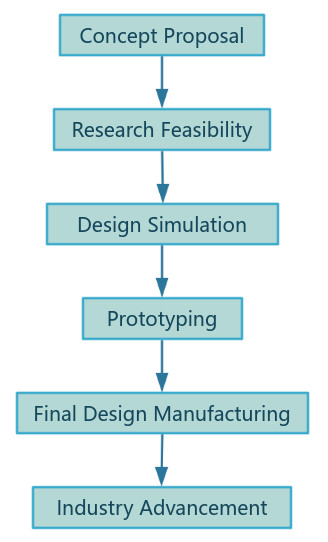
Creating a gear from concept to design involves several stages, including conceptualization, design, modeling, and validation. Here's a detailed guide to help you through each step.

From Concept to Design: The Process of Making Custom Gears
As a gear manufacturer, customers often throw an idea at us and ask us to design and develop the product ourselves. Our journey begins with a concept - the idea of creating precision-engineered gears that will drive machines and equipment with efficiency and reliability.
In the world of mechanical engineering and manufacturing, gears are the unsung heroes that keep the wheels of industry turning. From the smallest clockwork mechanism to the largest industrial machinery, gears play a crucial role in transmitting power and motion.
In conclusion, the journey from concept to design for a gear manufacturer is a complex and meticulous process that requires expertise, precision, and a deep understanding of mechanical principles.
Gear Design Phase
🚩 A blend of creativity and practicality, involving collaboration from various parties.
🎯 Aim is to meet specific mechanical requirements and performance standards.
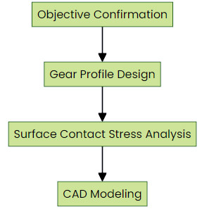
First, we need to confirm the design objectives with the client, such as transmission efficiency, load-bearing capacity, and service life requirements. Then, based on the principles of gear transmission, we proceed with gear profile design, gear surface contact stress analysis, and so on.
Objective Confirmation
1. Transmission Efficiency
2. Load-bearing Capacity
3. Service Life
4. Gear Profile Design
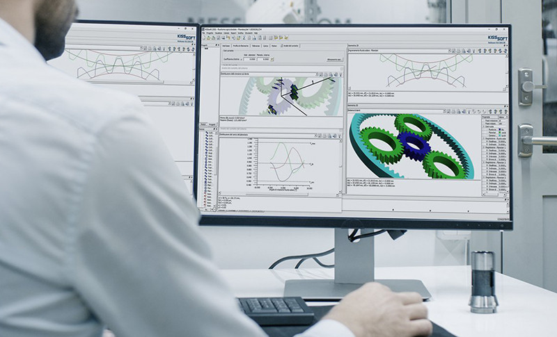
Design and Simulation
In this phase, we will design and simulate:
1. Gear Parameters: Determine basic parameters such as module (or diametral pitch), number of teeth, pressure angle, and gear ratio.
2. Materials Selection: Choose the appropriate material based on strength, wear resistance, and cost considerations.
The initial stage focuses on setting objectives and creating the gear's blueprint.
Tooth Shape
1. Pressure Angle
2. Module/Diametral Pitch
3. Gear Surface Contact Stress Analysis
Material Properties
1. Surface Hardness
2. Lubrication Considerations
3. CAD Modeling
3D Model Creation
1. Tolerance Setting
2. Simulation Testing
Prototyping
After the design has been refined and simulated, the next step is to create a physical prototype.
Prototype Creation: Use rapid prototyping methods such as 3D printing or CNC machining to create a prototype of the gear.
This phase involves material selection and the creation of a tangible gear prototype.
1. Material Selection
2.
Additive Manufacturing
3. Subtractive Manufacturing
4. Prototype Testing
Testing: Test the prototype under real or simulated conditions to check for performance, durability, and any potential issues.
This is often done using additive manufacturing techniques, such as 3D printing, which allow for rapid iteration and adjustments. The prototype is then subjected to rigorous testing to validate its performance against the initial specifications. Any issues discovered during this phase are addressed, and the design is revised accordingly.
Final Design and Manufacturing
With a successful prototype in hand, the final design is completed. This includes producing detailed manufacturing drawings and specifications that will guide the production process. The gear manufacturer must ensure that the design is optimized for the chosen manufacturing method, whether it be hobbing, shaping, or broaching, to ensure high quality and efficiency.
Feedback Analysis: Collect data from testing and identify areas for improvement.
Iterative Design: Modify the design based on feedback and re-test until the gear meets all requirements.
Summary Mind Map
The process from concept to design showcases attention to detail and a commitment to quality.
Tools and Resources:
1. CAD Software: SolidWorks, AutoCAD, Fusion 360
2. FEA Software: ANSYS, SolidWorks Simulation
3. Prototyping Tools: 3D Printers, CNC Machines
4. Material Databases: MatWeb, CES EduPack
PairGears take pride in our concept to design capabilities. Should you have any questions or require further assistance, please do not hesitate to contact our engineer: ben@pairgears.com.